Models
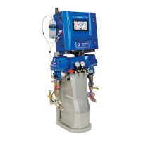
Reactor 2 E-XP2i
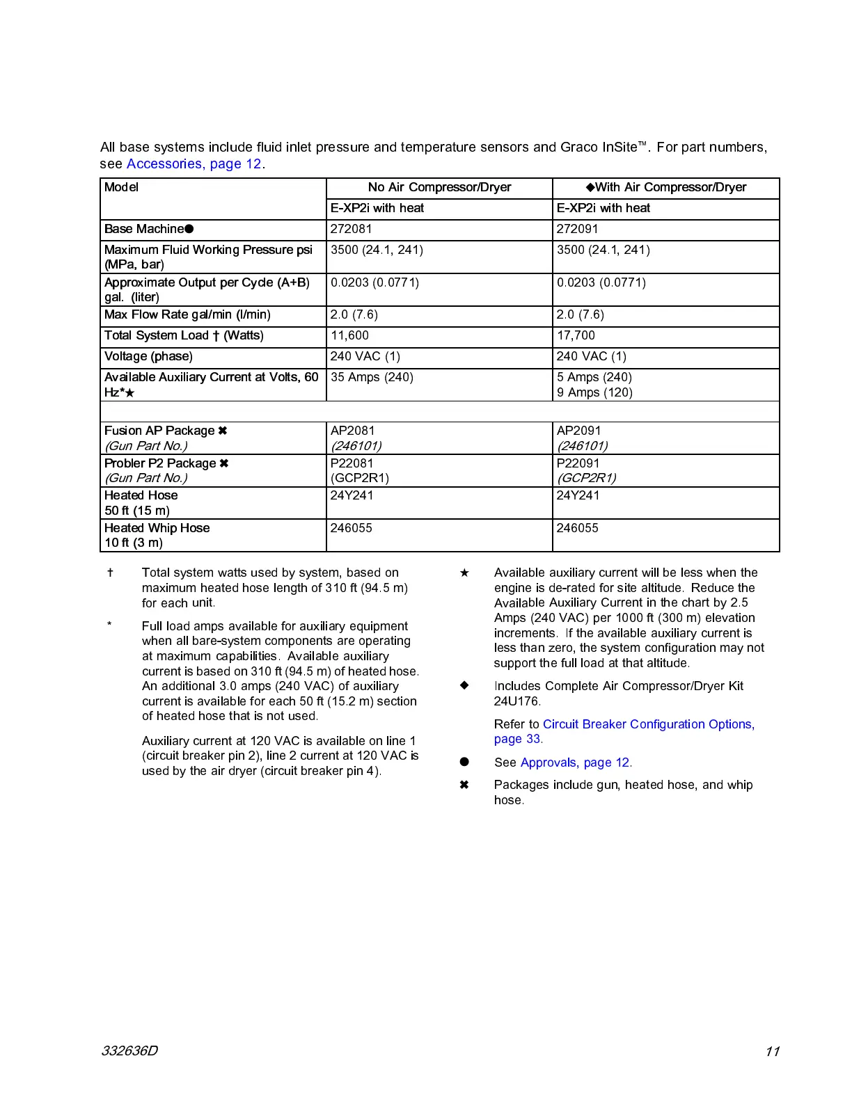
All base systems include fluid inlet pressure and temperature sensors and Graco InSite
™
. For part numbers,
see Accessories, page 12.
No Air Compressor/Dryer
With Air Compressor/Dryer
Model
E-XP2i with heat E-XP2i with heat
Base Machine
272081 272091
Maximum Fluid Working Pressure psi
(MPa, bar)
3500 (24.1, 241) 3500 (24.1, 241)
Approximate Output per Cycle (A+B)
gal. (liter)
0.0203 (0.0771) 0.0203 (0.0771)
Max Flow Rate gal/min (l/min)
2.0 (7.6) 2.0 (7.6)
Total System Load † (Watts)
11,600 17,700
Voltage (phase)
240 VAC (1) 240 VAC (1)
Available Auxiliary Current at Volts, 60
Hz*
35 Amps (240) 5 Amps (240)
9 Amps (120)
Fusion AP Package
(Gun Part No.)
AP2081
(246101)
AP2091
(246101)
Probler
P2 Package
(Gun Par
t No.)
P22081
(GCP2R1)
P22091
(GCP2R1)
Heated H
ose
50 ft (15
m)
24Y241 24Y241
Heated
Whip Hose
10 ft (3
m)
246055 246055
Total sy
stem watts used by system, based on
maximum
heated hose length of 310 ft (94.5 m)
for each
unit.
* Full load amps available for auxiliary equipment
when all bare-system components are operating
at maximum capabilities. Available auxiliary
current is based on 310 ft (94.5 m) of heated hose.
An additional 3.0 amps (240 VAC) of auxiliary
current is available for each 50 ft (15.2 m) section
of heated hose that is not used.
Auxiliary current at 120 VAC is available on line 1
(circuit breaker pin 2), line 2 current at 120 VAC is
used by the air dryer (circuit breaker pin 4).
Availa
ble auxiliary current will be less when the
engine
is de-rated for site altitude. Reduce the
Availa
ble Auxiliary Current in the chart by 2.5
Amps (2
40 VAC) per 1000 ft (300 m) elevation
increm
ents. If the available auxiliary current is
less th
an zero, the system configuration may not
suppor
t the full load at that altitu de.
Includes Complete Air Compressor/Dryer Kit
24U176.
Refer to Circuit Breaker Configuration Options,
page 33.
See Approvals, page 12.
Packages include gun, heated hose, and whip
hose.
332636D
11