Repair
38 309574C
Fluid Temperature Sensor
(FTS)
Test/Removal
2. Relieve pressure, page 8.
3. Remove tape and protective covering from FTS
(11), F
IG
. 14. Disconnect hose cable (F). Test with
ohmmeter between pins of cable connector.
4. If FTS fails test, replace FTS.
5. Disconnect air hoses (C, L), and electrical connec-
tors (D).
6. Disconnect FTS from whip hose (W) and fluid hoses
(A, B).
7. Remove ground wire (K) from ground screw on
underside of FTS.
8. Remove FTS probe (H) from component A (ISO)
side of hose.
Installation
1. Carefully extend FTS probe (H). Do not bend or kink
probe. Insert in component A (ISO) side of main
hose.
2. Connect whip hose ground wire (K) to ground screw
on underside of FTS.
3. Install FTS in reverse order of removal. Leave slack
(G) in cables as stress relief, to prevent cable failure.
4. Secure hose and cable connections with tape and
install protective covering.
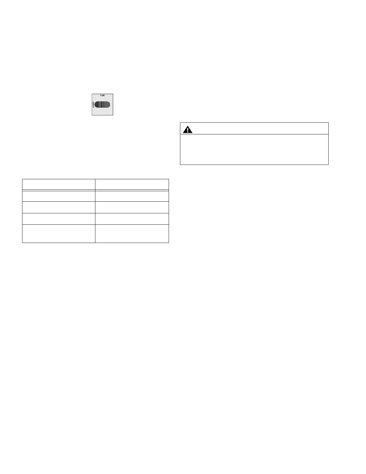
1. Turn main power OFF . Disconnect power
supply.
Pins Result
1 to 2 approximately 10 ohms
1 to 3 infinity (
∞
)
3 to FTS groundscrew 0 ohms
1 to FTS component A
fitting (ISO)
infinity (
∞
)
CAUTION
To prevent damage to probe, do not kink or exces-
sively bend whip hose. Do not coil hose tighter than
the minimum bend radius of 3 ft (0.9 m). Do not sub-
ject hose to excessive weight, impact, or other abuse.