Repair
40 309574C
Display Module
Temperature and Pressure Displays
2. Relieve pressure, page 8.
3. Refer to electrical diagrams.
4. Put on static conductive wrist strap.
5. Disconnect main display cable (20) at lower left cor-
ner of display module, F
IG
. 15.
6. Remove screws (409, 410) and cover (404).
7. Disconnect cable connectors J1 and J13 from back
of temperature display (401) or pressure display
(402).
8. Disconnect ribbon cable(s) (R) from back of display.
9. Remove nuts (408) and plate (405).
10. Disassemble display, see detail in F
IG
. 15.
11. Replace board (401a or 402a) or membrane switch
(401b or 402b) as necessary.
12. Reassemble in reverse order, see F
IG
. 15. Apply
medium strength thread sealant where shown. Be
sure display cable ground wire (G) is secured
between cable bushing and cover (404) with screws
(412). Also check ground connection at rear of
Reactor, see below.
CAUTION
Before handling board, put on a static conductive wrist
strap to protect against static discharge which can
damage board. Follow instructions provided with wrist
strap.
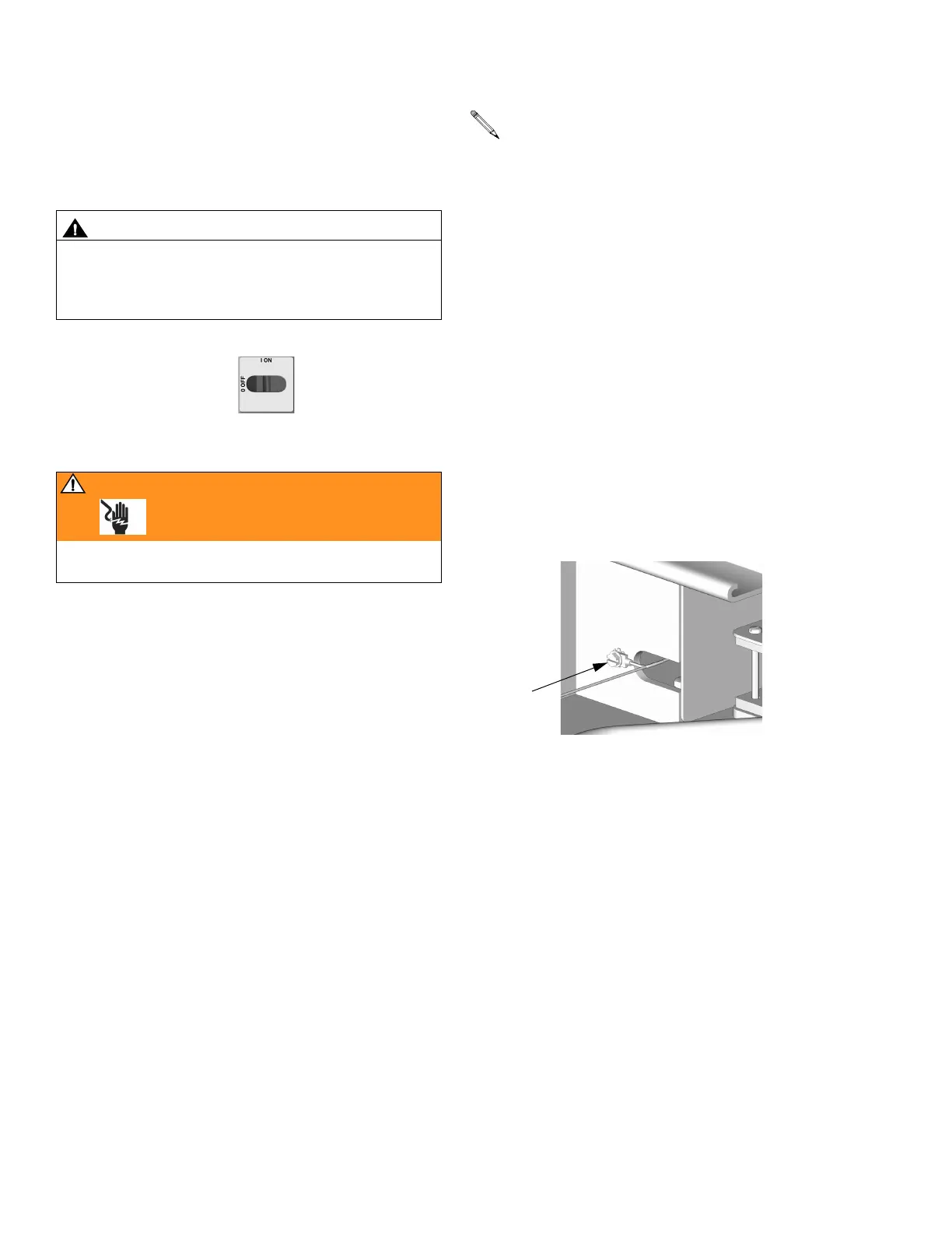
1. Turn main power OFF . Disconnect power
supply.
WARNING
Read warnings, page 5. Wait 5 min for stored voltage
to discharge (E-30 and E-XP2 models only).
If replacing both displays, label temperature dis-
play cables TEMP and pressure display cables
PUMP before disconnecting.
G
TI3743a