Repair
16 3A2989V
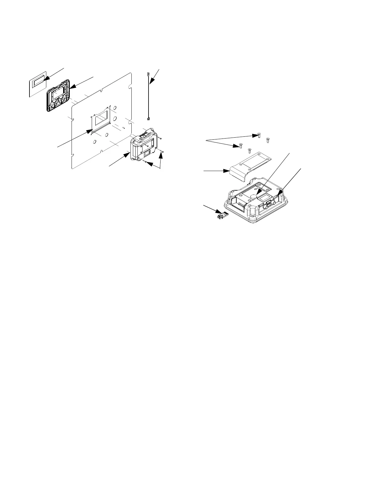
6. Remove front display panel (504d) and
gasket (504g).
7. Discard old display assembly.
8. Place new front display panel (504d) and
gasket (504g) on front panel of control box (16).
NOTE: To ease installation use clear tape to hold front
display panel in place.
9. Carefully connect display cables and key switch
cable to new circuit board.
10. Install new rear display panel (504c) and secure
with four screws (504f). Ensure key switch cable
protrudes from opening in top of display module.
11. Install access cover and screws.
12. Reconnect CAN cable to display module.
13. Reconnect power.
14. Load software. See Upgrade Software, page 16.
15. Replace shroud.
16. Configure system settings as they were set on old
display. See XM PFP Operation manual for instruc
tions.
Replace Front Panel
See Replace Display, page 15, for instructions.
Upgrade Software
1. Download all USB logs. The new software will erase
the USB logs. See operation manual for instructions
to Download Data from USB.
2. Turn off power to the system.
3. Remove Shroud and Front Panel of Control Box,
see page 13.
4. Remove four screws (504f) then remove access
cover (504e).
5. Insert and press token (506) firmly into slot.
NOTE: There is no preferred orientation of token.
6. Turn power on.
7. The red indicator light (L) will flash until new soft
ware is loaded on the display module.
8. All system modules will be automatically updated.
See Graco Control Architecture Module Program
ming manual for details.
9. Remove token.
10. Reinstall shrouds and front panel.
r_xm1a00_312359_313289_25a
504b
504c
504g
504d
Display Cable
539
L
506
504f
504e
Battery
r_xm1a00_312359_313289_2a
 Loading...