Home
Graco
Paint Sprayer
Simulation XM
Graco Simulation XM Repair Parts
4
of 1
of 1 rating
86 pages
Give review
Manual
Specs
To Next Page
To Next Page
To Previous Page
To Previous Page
Loading...
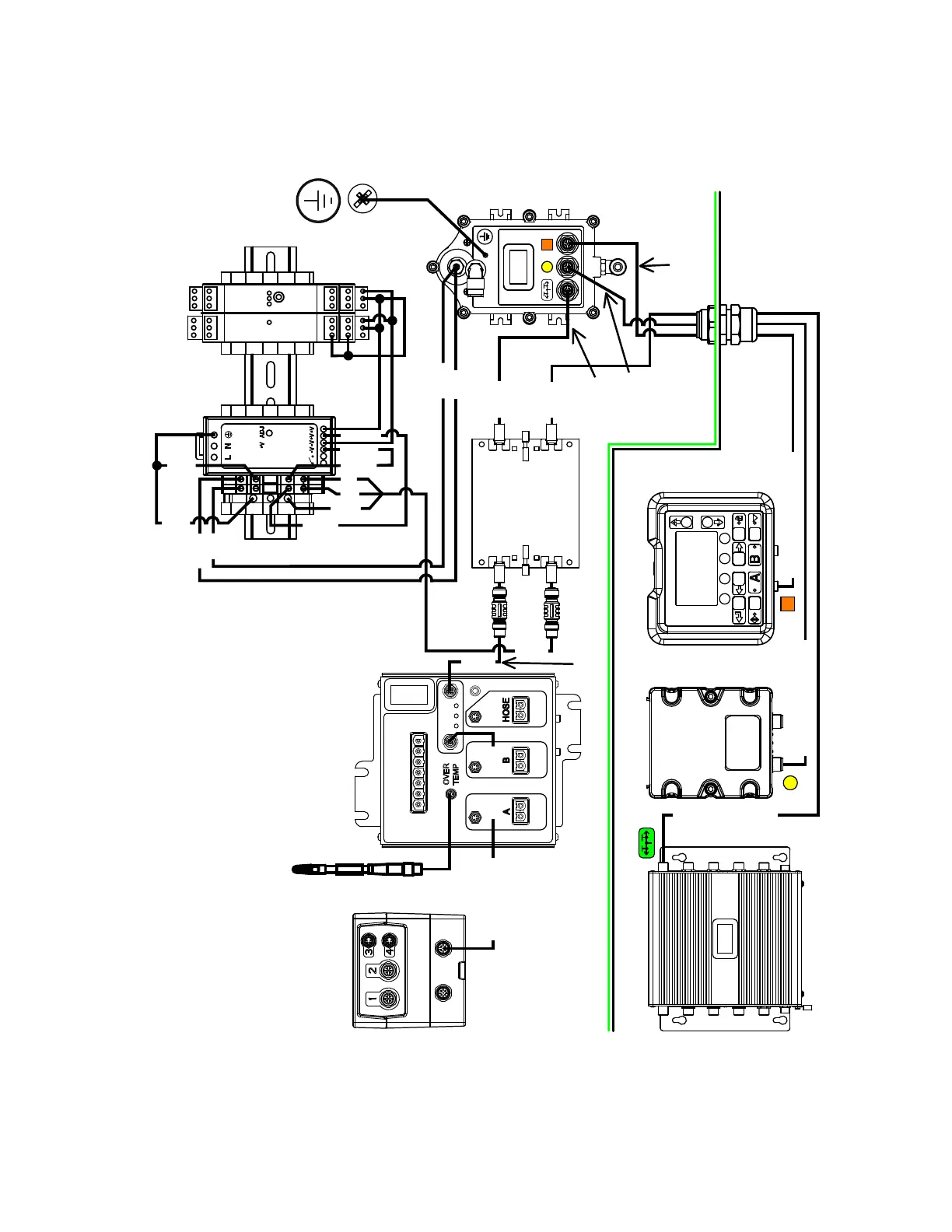
Electrical Schematics
3A2989V
41
CAN Network and DC
Power Schematic
TCM-1
24Y169
Over-T
emperature
Swich Short
24U109
CAN Network
Isolato
r
24M485
Multi-Zone
IS Barrier
24W610
Power Supply
and Isolators
DIN Rail 17D228
PS1-GND
TB17
TB19
TB19
TB18
PS1-V+
PS1-V
-
Red
Black
TL-7
TL-10
HR-15
HR-14
TL-14
TL-15
Red
Black
GND
V+
V-
Cord Grip 126881
Nut 126891
Gromet 127837
Purge Box
Control Box
Purge Box
Control Box
Fluid Control
FCM-1 289696
Base 289697
Fluid Control
FCM-2 255920
USB
289900
Base
289899
DM Front
255727
Display Module 288997
Both Switches
Pushed In
CAN Power Cable
24R735
CAN Cable
1M 127068
CAN Cable
1M 127068
CAN Cable
0.5M 15V778
CAN Cable 1.9M 17D261
CAN Cable 1.5M 17D257
CAN Cable 1.6M 17D260
Ground Wire
194337
CAN-1
CAN-2
CAN-3
CAN-4
CAN-2
CAN-1
CAN-4
CAN-3
CAN-TCM-2
CAN-TCM-1
CAN-FCM1-2
Orange Square Label
Y
ellow Circle Label
Green Com Label
White Com
Label
Y
ellow Circle
Label
Orange Square
Label
17D226
17D227
126453
A
dapter
16T072
PS1
T
ank Level
Hose
RTD
7
8
9
10
11
12
13
14
15
7
8
9
10
11
12
13
14
15
1
2
3
4
56
1
2
3
4
56
24
VDC
TB17
TB18
TB19
18
A
WG Copper Wire
16
A
WG Copper Wire
NOTE: 2 in. separation required bet
ween CAN cables 17D257,
17D260, 17D261, and TCM-1 24Y1
69.
NOTE: 2 in. separation required bet
ween CAN cables 127068,
24R735, and the top half of isola
tors 17D226, 17D2
27.
40
42
Table of Contents
Related Manuals
2
Table of Contents
2
Models
3
Warnings
4
Keep Components a and B Separate
6
Changing Materials
6
Components a and B
6
Component Identification
6
Grounding
6
Pressure Relief Procedure
7
Flush Mixed Material
9
Troubleshooting
10
Repair
11
Replace Air Filter Element
11
User Interface/Control Box
13
Junction Box
17
Purge Box
18
Air Controls
21
Dosing Valve Assembly
23
Sensors
24
Pump Assembly (System Module)
25
Pail Feed RAM Pump Assembly (Feed Module)
26
Flush Pump
26
Heaters
27
Replace Radar Level Sensor
28
Set up a New Radar Level Sensor
29
Electrical Schematics
31
Non-Hazardous Location Schematic
31
Hazardous Location Schematics
38
Parts
47
XM PFP System Subassemblies
48
Base System (262878, 262941) Subassemblies
61
Feed Module Sub-Assemblies
75
Accessories
81
Technical Data
82
Dimensions
84
Graco Standard Warranty
86
Graco Information
86
Other manuals for Graco Simulation XM
Setup & Operation
100 pages
Instructions - Parts
22 pages
Instructions-Parts List
14 pages
4
Based on 1 rating
Ask a question
Give review
Questions and Answers:
Need help?
Do you have a question about the Graco Simulation XM and is the answer not in the manual?
Ask a question
Graco Simulation XM Specifications
General
Brand
Graco
Model
Simulation XM
Category
Paint Sprayer
Language
English
Related product manuals
Graco XM
32 pages
Graco XM PFP
100 pages
Graco XM Series
106 pages
Graco SG2
4 pages
Graco ST Max 395
2 pages
Graco Spray Station
2 pages
Graco Standard Series
70 pages
Graco field lazer s100
67 pages
Graco EM 480 Hydra-Spray
24 pages
Graco Sharpe Finex FX1000
32 pages
EH 333 HYDRA-SPRAY A Series
20 pages
390 Electric Airless Sprayer
32 pages
 Loading...