Electrical Schematics
42 3A2989V
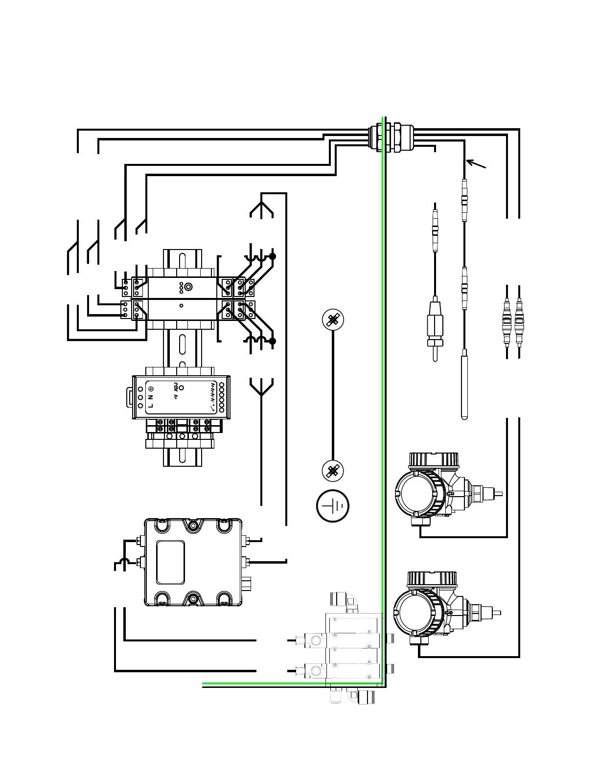
Sensors Schematic Purge Box
Power Supply
and Isolators
DIN Rail 17D228
Cord Grip 126881
Nut 126891
Gromet 127838
Purge Box
Solenoid Module
Tank Fill
2
1
6
75
Fluid Control
FCM-1 289696
Base 289697
Sol
Sol B
TL-9
TL-8
TL-11
TL-12
HR-7
HR-8
HR-11
HR-10
17C056
Tank Level Cable 17D201
Hose RTD Cable 17D202
Solenoid Cable 121806
Solenoid Cable 121806
BRO-5
BRO-2
BLU-3
BLU-6
Hose Heater RTD Cable 17D200
Hose Bundle RTD Cable 17D199
BRO-1
BRO-4
BLU-6
BLU-3
Tank Level B Cable 17D198
Tank Level A Cable 17D197
Level Sensor
24X090
Level Sensor
24X090
Hose Bundle RTD 24P242
Hose Heater RTD 126427
Compression Fitting 126351
B
Large Door Ground Wire
194337
Level Sensor Cable 128026
Level Sensor Cable 128026
M8 Connectors
M12 Connector
M8 Connectors
SOL-
SOL-B
FCM1-1
FCM1-2
B TANK LEVE
TANK LEVE
B TANK LEVE
TANK LEVE
FCM1-7
FCM1-6
PS1
Tank Level
Hose
RTD
7
8
9
10
11
12
13
14
15
7
8
9
10
11
12
13
14
15
1
2
3
4
56
1
2
3
4
56
24
VDC
M8 Connectors
Extension 125357
HOSE RTD
HOSE HEATER RTD
TANK LEVEL
TANK LEVEL
18 AWG Copper Wire
NOTE: 2 in. separation required between sensor cables 17D201, 17D202
and CAN network isolator 24M485 on previous page.
 Loading...