Pressure Control Board
26 311365H
110 Vac U.K. Motor Control Board
Removal
1. Remove four screws (38) and cover (96).
2. Disconnect display connector (A) from motor
control board.
3. Remove bottom two screws (39) and allow
control panel (68) to hang down freely.
4. Disconnect control board power lead(s) (D)
from ON/OFF switch (33) and motor control
board (52).
5. Disconnect potentiometer connector (C) from
motor control board.
6. Disconnect WatchDog (49) switch connector
(X) from motor control board.
7. Disconnect 15/20A switch (178) (1595 model
only).
8. Disconnect transducer connector (E) from
motor control board.
9. Disconnect motor connectors (F, G, and H)
from motor control board.
10. Remove motor shroud. Disconnect and remove
wiring from baffle.
11. Remove nut and screw (88) and disconnect
ground wire (87). Disconnect coil connector
(Y). Remove coil (81).
12. Remove top two screws (39) and control box
(61).
13. Remove six screws (27), two screws (102) and
control board.
Installation
1. Use Acetone or equivalent solvent to
thoroughly remove thermal paste from the
pockets of the Powerbar.
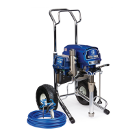
2. Apply thermal compound:
a. For 2 capacitor boards and 6 capacitor
boards with the Powerbar shown in Figure 1
below, apply a small amount of thermal
compound 15U114 or 110009 (5) to shaded
component areas on rear of motor control
board (52)
.
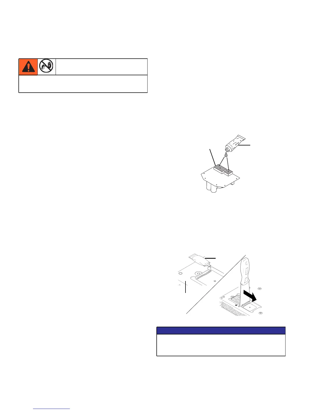
b. For 6 capacitor boards with the powerbar
shown in Fig. 2 below, apply a small
amount of thermal compound 15U114 or
110009 (5) into both pockets of the Power-
bar (69) and scrape across the pocket with
the provided scraper so an even layer is
remaining in the pocket
Relieve pressure; page 9. Wait 5 minutes before
servicing.
NOTICE
To reduce risk of motor control board failure, do
not overtighten screws (102) which can damage
the electric components.
5
52
ti17334a
Figure 1
5
69
Figure 2
ti14693a
 Loading...