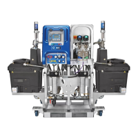
Installation and Setup
313292J 19
Installation and Setup
See Dimensions, page 27, to aid in component
installation.
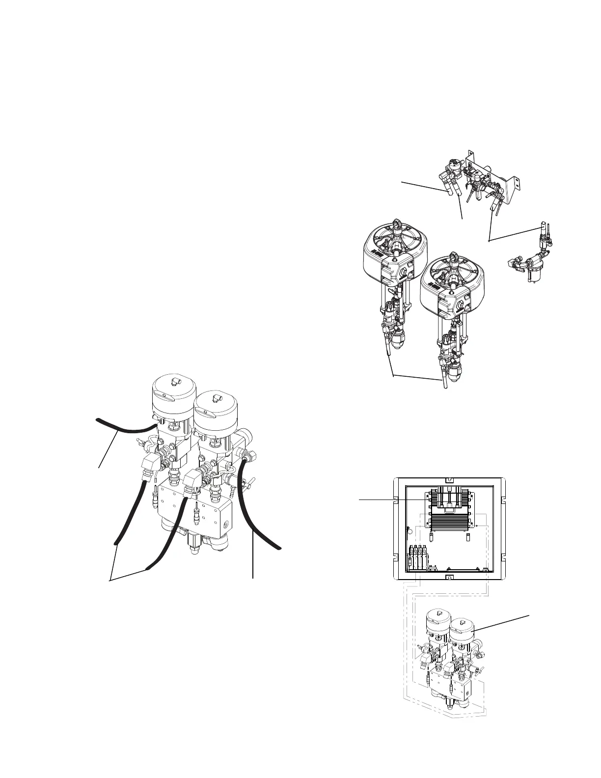
Connect Air Lines
Refer to component identification in FIG. 1, page 11.
Refer to the pneumatic schematic drawings in the XM
Plural-Component Sprayer repair-parts manual 313289
for guidance.
• Connect air lines (68, 69) between the fluid control
assembly (B) and the control box (C).
• Connect air lines (68, 69) between the air controls
assembly (E) and the control box.
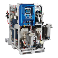
Connect Fluid Hoses
Use the following illustration as a guide to connect the
fluid hoses.
Connect Air Hoses
• Connect air hose (12) between air inlet manifold and
air controls assembly. (Hose called out as 12(C)).
• Connect air hose (12) between air controls
assembly and both air motors. Hose called out has
12(A) and 12 (B).
Connect Sensor Cables
Connect pressure and temperature sensor cables
(supplied with fluid control assembly (B)) to the fluid
control module.
Recirculation
Hose (gray)
Hose to Pump
Lower (black)
Recirculation
Hose (gray)
WLD
12 (A and B)
12(C)
12(B)
12(A)
r_xmaa00_313292_4a
B
Fluid
Control
Module
 Loading...