Boiler Installation
Information
15
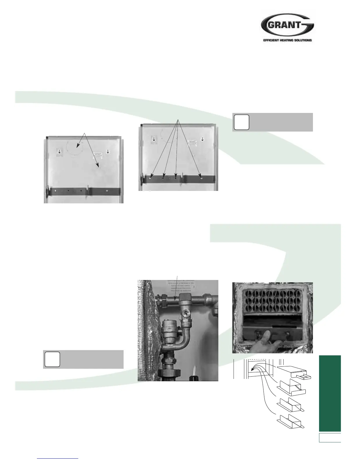
Figure 4-8: Installing the back panel
Figure 4-9: Fixing the back panel
7. Locate the mounting bracket on to
the back panel, aligning the four
holes in the bracket with those in
the back panel. Ensure that the
mounting ‘hooks’ are pointing
upwards and secure using the
f
ixings supplied by Grant UK.
8. Lift the boiler shell and hang it on the
mounting bracket – ensuring that the
mounting plates on either side of the
shell are fully located in the vertical
slot of both mounting hooks.
9. Re-fit the return pipe to top right
hand connection on boiler shell.
Pass return pipe from system
through hole in back panel (either at
top or bottom of panel, as required)
and connect to boiler return pipe.
11. Non-system model – Re-fit flow pipe
to compression connection on boiler
shell. Pass flow pipe from system
through hole in back panel (either at
top or bottom of panel, as required)
and connect to boiler flow pipe.
10. System model only - Re-fit pump
complete with flow pipe to upper
pump union on boiler shell. Ensure
that rubber pump union washer is
fitted. Pass flow pipe from system
through hole in back panel (either at
top or bottom of panel, as required)
and connect to boiler flow pipe.
Figure 4-10: Re-fitting flow & return pipe
Figure 4-11: Re-fitting baffles into
boiler shell
4
.5 Installing the Boiler
You are now ready to install the boiler.
The procedure is as follows:
1. If a back outlet flue system is to be
used, remove the large circular flue
knockout from back panel. If the rear
outlet PRV discharge is to be used,
remove the knockout from the back
panel (as shown in the figure below.
If side outlet flue is to be used (to
either left or right) then mark position
as it may be necessary to cut flue hole
BEFORE installing boiler on to wall.
6. Remove the back panel from the
wall. Drill the holes for the mounting
bracket fixings and fit the wall plugs
provided. Drill all other necessary
holes. If required, core drill the wall
for a back outlet flue and drill a hole
for the PRV discharge pipe.
Re-mount the back panel on the
two keyholes slots.
!
NOTE
I
t is recommended that the system
flow and return pipes are connected to
the boiler at this point in the
installation. Two 22mm isolating valves
are supplied for use with sealed
system models only. These must not
be used on an open vented system.
These boiler isolating valves should
be located adjacent to the boiler in a
convenient position.
12. Re-fit burner. First remove burner
securing nut, locate burner head
into hole in burner flange/boiler shell
and locate mounting screw through
hole on top of burner. Re-fit nut and
tighten to secure burner in place.
Connect flexible oil lines from oil
supply pipework to burner. It is
recommended that the copper oil
lines are installed at this stage while
the side panels are not in place.
13. Re-fit baffles into boiler shell –
ensuring they are in the correct
order (check marking on each baffle)
as shown below
!
NOTE
1
2
3
4
2. Locate and hold the back panel in the
required position on the wall. Check it
is level using a spirit level on the top
flange. Mark position of the holes for
the two keyhole slots. Remove the
back panel from the wall.
3. Drill and fit wall fixing plugs (not
supplied) in the two holes. Fit suitable
screws and mount the back panel on
the wall using the two keyhole slots.
Check again that the back panel is
level before proceeding.
4. Mark the position of the four
mounting bracket fixings on to the
wall from the back panel. Also mark
the positions of the flow and return
pipes, the cold mains (for filling
loop), the electrical power supply,
and the condensate discharge pipe.
5. If using a back outlet flue and/or
rear PRV outlet is to be used, also
mark these holes on to the wall.