107
Programming example: fi xed-wing model
Programming example: servos running in parallel
In some cases a second servo is required to run in
parallel with an existing servo; for example, if a second
elevator or rudder is to be actuated by a separate servo,
or where a second servo is needed to cope with very
high control forces, or where two servos are required for
a large control surface due to the high forces involved.
This task could be solved simply by connecting both ser-
vos together in the model using a conventional Y-lead.
However, this has the drawback that the linked servos
cannot be adjusted individually from the transmitter, i. e..
you forfeit the basic advantage of the computer radio
control system: separate adjustment of individual servos
from the transmitter.
Another option would be to use a “magic box” module
(Order No. 3162 – available in the Graupner range) in-
stead of a simple Y-lead. This unit allows one transmitter
channel to control up to four servos, which can then be
adjusted in direction of rotation, centre and travel; see
the Appendix for further details.
However, the simplest method is to use the transmitter’s
software facilities. For example, it is easy to set up …
Two elevator servos
… to operate in parallel. First move to the …
»base sett.« (pages 46 … 49)
SEL
2 elev sv
1
GRAUBELE
model name
stick mode
tail type
motor on C1
no
… menu and set “2 elev sv” in the “Tail” line.
The tw
o elevator servos are then connected to receiver
output sockets 3 and 8.
Two rudder servos
In this example we will connect two rudders “in parallel”
using the »free mixer« menu. The second rudder could
be connected to receiver output 8, which is not already
in use.
The fi rst step is to move to the …
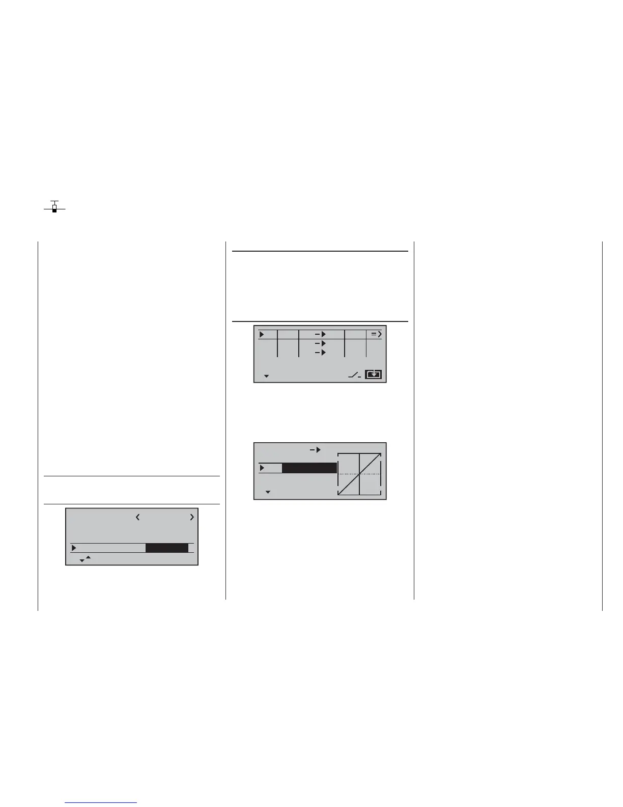
»free mixer« (pages 89 … 93)
SEL
SEL
typ fro
to
M1
M2
M3
rd
??
8
??
??
??
tr
… menu and set up a mixer “tr rd ¼ 8”.
In the “Type”
column select the “tr” setting, so that the rudder trim
affects both rudder servos.
Finally switch to the graphics page and set a SYMmetri-
cal mixer input of +100%:
MIX 1 tr rd 8
trv
0%offs
ASYSYM
+
100%
+
100%
+
Once again, for safety reasons it is really essential that
you set or leave input 8 to “empty” in the »contr set.«
menu.
As an added refi nement, you may want both rudders
to defl ect outwards only, as part of a braking system
controlled by the Ch 1 stick. This can be accomplished
by setting up two additional mixers “c1 ¼ 4” and “c1
¼ second rudder channel”, with suitable servo travel
settings. An offset of +100% is then selected for both
mixers, as the Ch 1 stick is (usually) at its top end-point
when the airbrakes are retracted, and the winglet rud-
ders are only required to defl ect outward proportionally
when the brakes are extended.