92
Program description: free mixers
Symmetrical mixer ratios
The next step is to defi ne the mixer values above and
below the mixer neutral point, starting from the cur-
rent position of the mixer neutral point. Select the SYM
fi eld, so that you can set the mixer value symmetrically
relative to the offset point you have just programmed.
Press the rotary cylinder, then set the values in the two
highlighted fi elds within the range -150% to +150%.
Remember that the set mixer value always refers to the
signal from the associated transmitter control (control
signal)! Setting a negative mixer value reverses the
direction of the mixer.
Pressing the CLEAR button erases the mixer ratio in the
highlighted fi
eld.
The “optimum” value for our purposes will inevitably
need to be established through a fl ight testing pro-
gramme.
MIX 1 6
+
20%
+
20%
75%
ASYSYM
el
trv
offs
Since we previously set the mixer neutral point to -75%
of control tr
avel, the elevator (“el”) will already exhibit a
(slight) “down-elevator” effect at the neutral point of the
landing fl aps, and this, of course, is not wanted. To cor-
rect this we shift the mixer neutral point back to -100%
control travel, as described earlier.
MIX 1 6
+
20%
+
20%
100%
CLRSTO
el
trv
offs
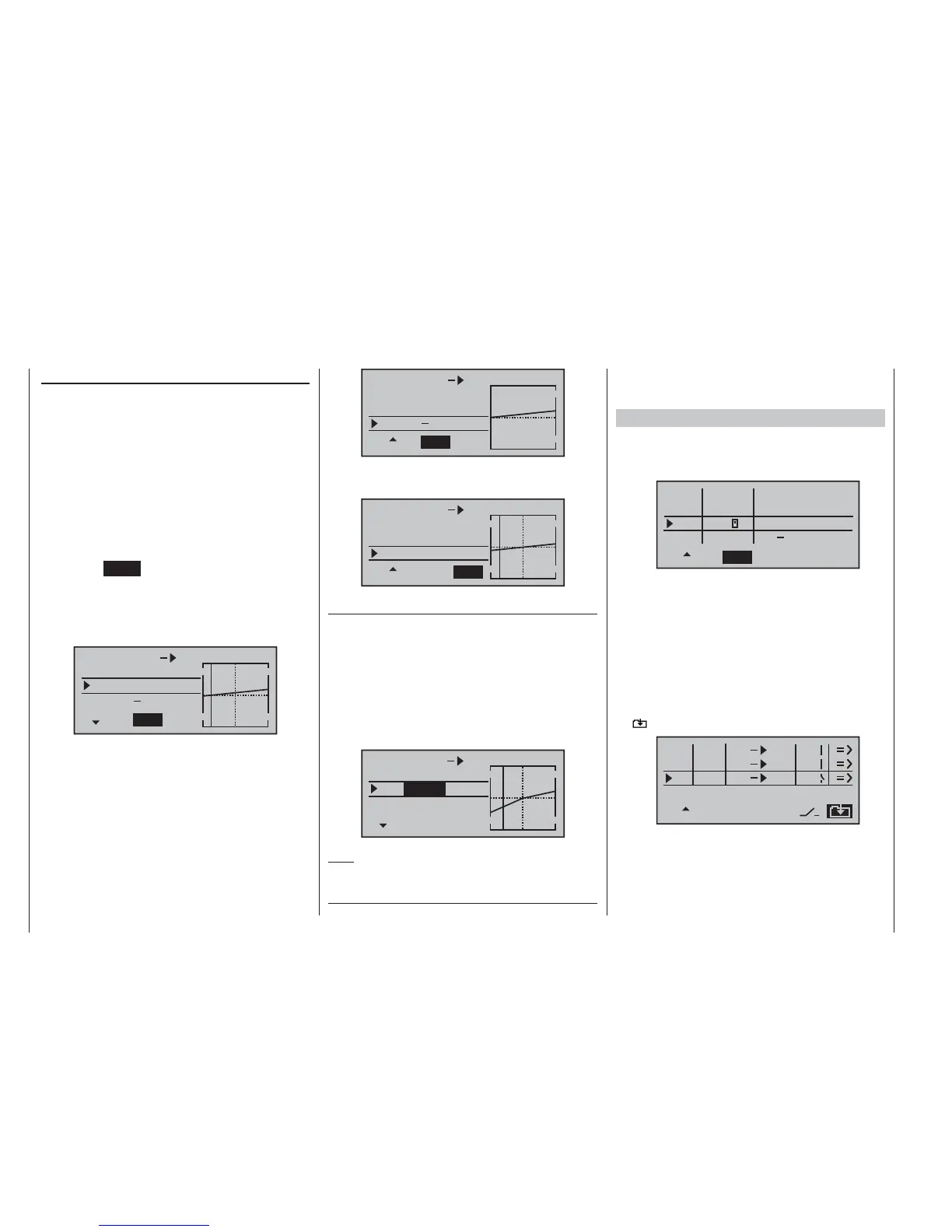
If you were now to reset the offset from -75% to, say, 0%
control tr
avel, the screen would look like this:
MIX 1 6
+
20%
+
20%
0%
STO
CLR
el
trv
offs
Asymmetrical mixer ratios
F
or many applications it is necessary to set up different
mixer values on either side of the mixer neutral point.
If you set the offset of the mixer used in our example (“6
¼ el”) back to 0%, as shown in the picture above, then
select the ASY fi eld and turn the rotary proportional
control in the appropriate direction, the mixer ratio for
each direction of control can be set separately, i. e. to left
and right of the selected offset point:
MIX 1 6
+
44%
+
22%
0%
SYM ASY
el
trv
offs
Note:
If y
ou are setting up a switch channel mixer of the “S ¼
N.N.*” type, you must operate the assigned switch to
achieve this effect. The vertical line then jumps between
the left and right sides.
Examples:
To open and close the aero-tow release the switch 1.
SW 3 has already been assigned to control channel
8 in the »contr set.« menu.
I6
I7
I8
+
trv
100%
100%
100%
100%
100%
100%
SEL
SYM
ASY
3
ctrl7
empty
++
++
++
In the meantime you have carried out a few aero-tow
fl ights, which showed that you always needed to hold
in slight up-elevator during the tow. You now wish to
set the elevator servo (connected to receiver output
3) to slight “up” trim when the tow release is closed.
In the screen familiar from page 89 we have set up
the third linear mixer to accomplish this, using the
switch channel “S” as the mixer input. Now move the
selected switch to the OFF position, and select the
symbol …
SEL
SEL
M1
M2
M3
6
S
1
3
typ fro
to
c1
el
el
el
C1
… to move to the second page. Hold the rotary cyl-
inder pressed in to select the
“Offs” line, and press
the rotary cylinder again: the offset value jumps to
+XXX% or -XXX%, depending on the selected switch
position.
* N.N. = Nomen Nominandum (name to be stated)