14
Description of transmitter: transmitter controls
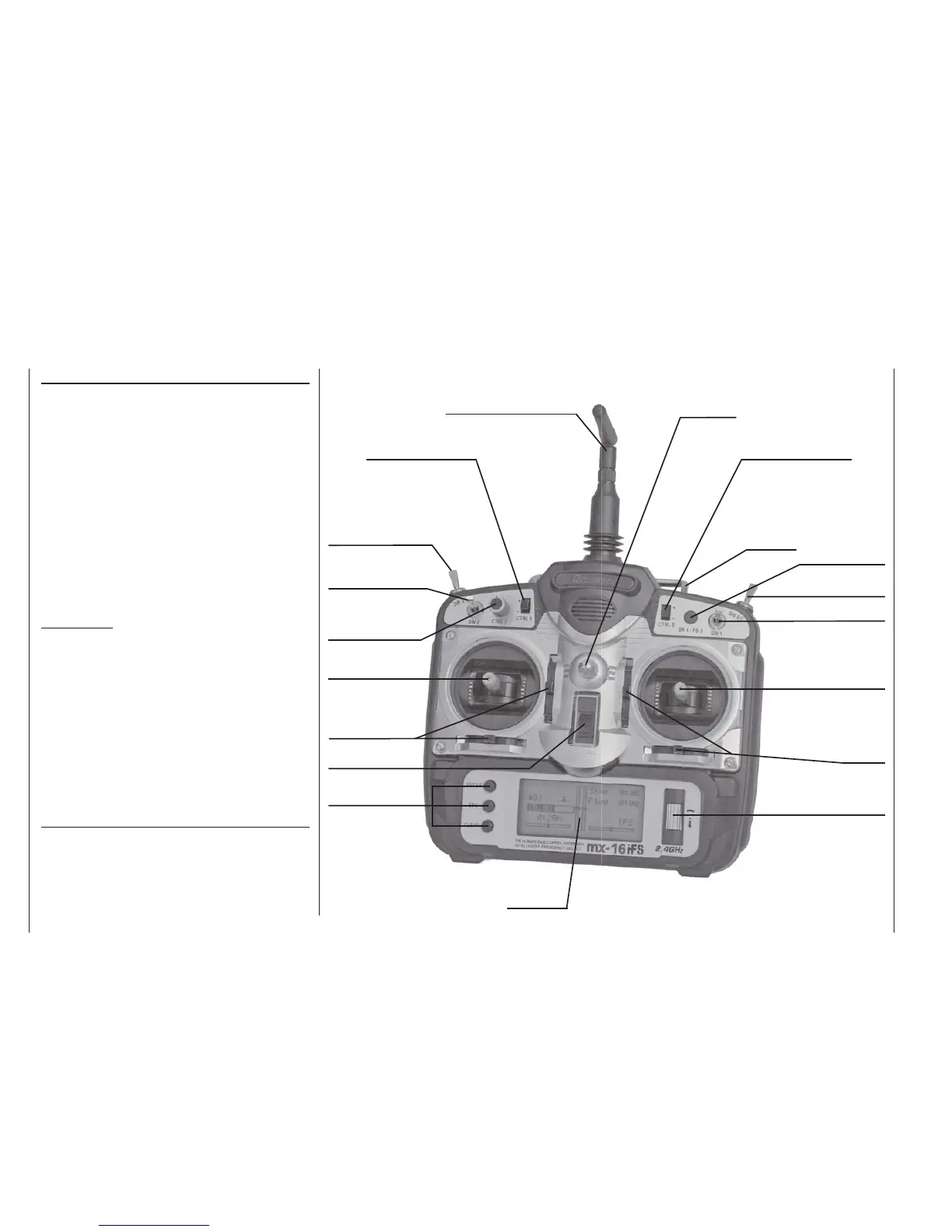
Description of transmitter
Transmitter controls
Aerial with folding / swivelling joint
CTRL 6: INC / DEC buttons*
SW 3: two-position switch
SW 2: two-position switch
CTRL 7: rotary proporti-
onal control
Left-hand stick unit
Trim buttons
ON / OFF switch
Input buttons
LCD screen
Rotary cylinder
Trim buttons
Right-hand stick unit
SW 1: two-position switch
Button: SW 4 / PB 8
Carry handle
Neckstrap lug
Attaching the transmitter neckstrap
You will fi nd a strap lug mounted in the centre of the
front face of the
mx-16iFS transmitter, as shown in the
drawing on the right. This lug is positioned in such a
way that the transmitter is perfectly balanced even when
suspended from a neckstrap.
Order No. 1121 Neckstrap, 20 mm wide
Order No. 70 Neckstrap, 30 mm wide
SW 6 / 7: three-position switch
* INC/DEC buttons (CTRL 5 and 6
Each time you press the button the servo travel changes by 1% of
the set maximum; the system works as follows:
INC – in the positive direction;
DEC – in the negative direction.
The button position is also stored separately for each fl ight phase.
CTRL 5: INC / DEC buttons*
Important note:
In the transmitter’s standard form any servos connected
to the receiver can initially only be operated using the
dual-axis sticks. For maximum fl exibility, all the other
transmitter controls (CTRL 5 ... 7, SW 1 ... 7) are “free”
in software terms, and can be assigned to any channels
you like, enabling you to set up the system to suit your
personal preference or the requirements of a particular
model. This is carried out in the »contr set.« menu, as
described on pages 58 and 60.