72
Program description: wing mixers – fi xed-wing model
Fixed-wing mixers
ail
ail
diff aile.
rudd
flaps
+
0%
brak
brak
brak
elev
flap
aile
elev
elev
flap
flap
aile
elev
flap
diff–red
aile
SEL
+
0%
+
0%
+
0%
+
0%
+
0%
+
0%
+
0%
+
0%
+
0%
+
0%
+
0%
diff. flaps
(The display varies according to the information you
ha
ve entered in the “Motor on Ch 1” and “aile / fl ap” lines
in the »base sett.« menu. The selection above equates
to the setting “no (motor)” and “2ail 2fl ”.)
The
mx-16iFS transmitter’s program contains a series
of pre-programmed coupling functions, and all you have
to do is set the mixer ratios and (optionally) assign a
switch. The number of pre-programmed mixer functions
in the mixer list will vary according to the pre-set “model
type” (tail type, number of wing servos, with or without
motor – see the section starting on page 46). For ex-
ample, if your model is not fi tted with camber-changing
fl aps, and you have not entered any fl ap servos in the
»base sett.« menu, the software automatically sup-
presses all the fl ap mixers, as are the “Brake ¼ N.N.*”
mixers if you enter “Idle forward” or “Idle back” in the
“Motor on Ch 1” line. This makes the menus clearer and
easier to understand, and also avoids potential program-
ming errors.
Notes:
There are various alternative methods of positioning •
the camber-changing fl aps; these include:
a) Settling on just one position per fl ight phase,
simply by setting appropriate trim values in the
»phase trim« menu;
b) Controlling the fl aps manually using any trans-
mitter control assigned to “Input 6” (in the »con-
tr set.« menu – see page 58), after setting the ba-
sic fl ap positions in the »phase trim« menu, as
described earlier. Ideally the transmitter control
would be one of the INC / DEC controls (CTRL 5
or 6), as their positions are stored separately for
each fl ight phase.
The selected transmitter control directly operates
the two fl ap servos connected to receiver outputs
6 and 7, assuming that you have specifi ed fl aps in
the “Aile / fl ap” line of the »base sett.« menu. The
same control determines the fl ap setting of the ai-
lerons via the percentage value entered in the
“fl ap ¼ aile” mixer line.
For fi ner control of the fl ap positions, we recom-
mend that you reduce their travel to about 25% in
the »contr set.« menu.
c) It is also possible to leave the default setting of
“0%” in the appropriate line “fl ap ¼ aile” of the
»wing mixer« menu, and to assign the same
transmitter control to both input 6 and input 5 in
the »contr set.« menu. The magnitude of the ef-
fect on the two pairs of wing fl aps can then be ad-
justed using the servo travel adjustment facility.
If a transmitter control is assigned to input “7”, it will •
be de-coupled by the software if two camber-chang-
ing fl aps are defi ned; this is intentional, as it elimi-
What is a mixer?
The basic function
In many models it is often desirable to use a mixer to
couple various control systems, e. g. to link the ailerons
and rudder, or to inter-connect a pair of servos where
two control surfaces are actuated by separate servos. In
all these cases the signal which fl ows directly from the
“output” of a transmitter stick to the associated servo
is “bled off” at a particular point - this effect can also
“concealed” in transmitter control options such as »D/R
expo« or »contr set.« – and the derived signal is then
processed in such a way that it affects the “input” of an-
other control channel, and therefore eventually another
receiver output.
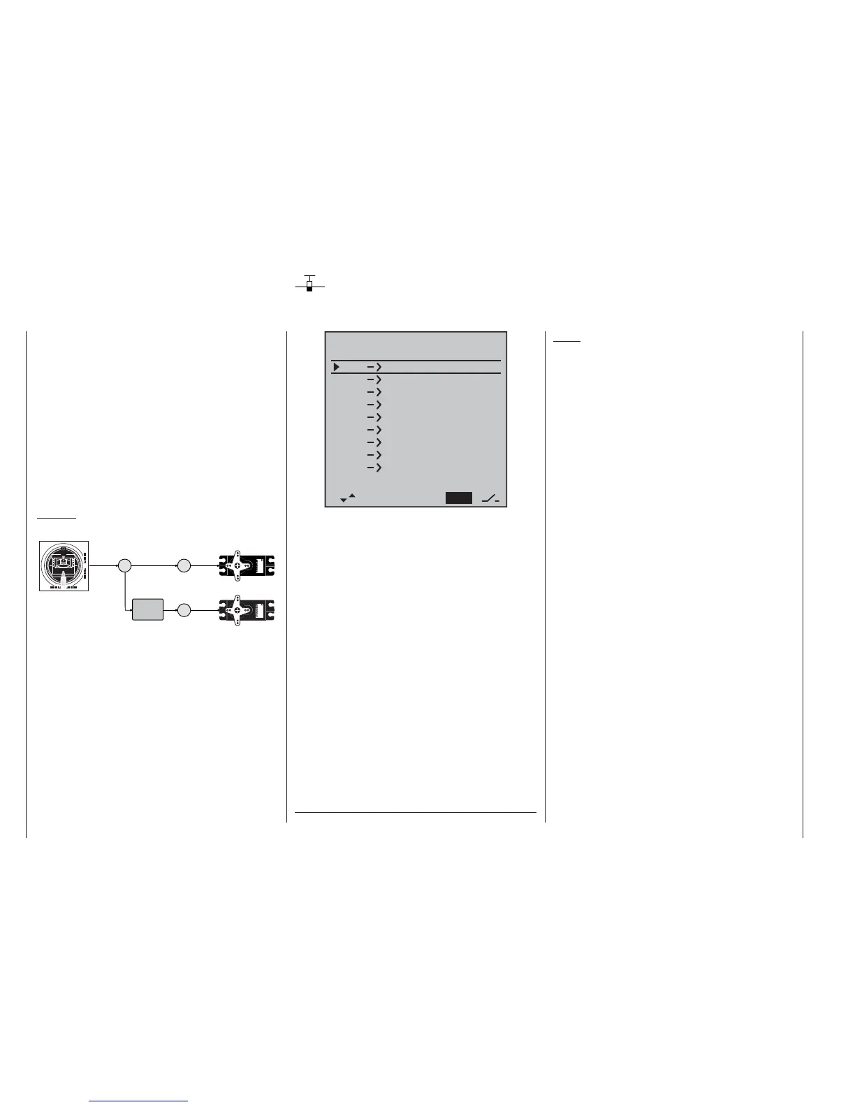
Example:
Controlling two elevator servos using the elevator stick:
3
3
8
Servo
4,8 V
C 577
Best.-Nr. 41 01
Servo
4,8 V
C 577
Best.-Nr. 4101
Function
input
Control channel
(receiver output)
Servo 1
Servo 2
Mixer
Transmitter
control
The mx-16iFS transmitter software contains a large
number of pre-programmed coupling functions as
standard, designed to mix together two (or more) control
channels. The mixer required in this example is sup-
plied “ready-made” in the software, and just has to be
activated in the “tail” line of the »base sett.« menu in the
form of “2 elev sv”.
The software also includes three freely programmable
linear mixers in the fi xed-wing and helicopter programs,
all of which can be used in each model memory.
For more information please refer to the general notes
on »free mixer« in the section of this manual starting on
page 88.
* N.N. = Nomen Nominandum (name to be stated)