41
Model helicopters: installation and connections
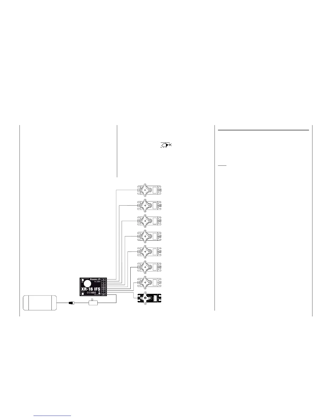
1 = PCollective pitch or roll-axis
(2) or pitch-axis (2) servo
2 = Roll-axis (1) servo
3 = Pitch-axis (1) servo
5 = Free, or pitch-axis (2) servo
4 = Tail rotor servo (gyro)
6 = Throttle servo
(speed controller)
7 = (Gyro gain)
8 = (Speed governor)
Receiver socket assignment for model helicopters
Note for modellers upgrading from earlier GRAUP-
NER systems:
Compared with the previous receiver channel sequence,
servo socket 1 (collective pitch servo) and servo socket
6 (throttle servo) have been interchanged. The servos
MUST be connected to the receiver output sockets in
the order shown at bottom right. Outputs not required
are simply left vacant. For more information on the differ-
ent types of swashplate, please refer to the »base sett.«
menu described on page 51.
All menus which are relevant to model helicopters are
marked with a “helicopter” symbol in the “Program
descriptions”:
This means that you can easily skip irrelevant menus
when programming a model helicopter.
Installation notes
The servos MUST be connected to the receiver
outputs in the order shown on this page. Outputs not
required are simply left vacant.
Please note the additional information on the follow-
ing pages.
Note:
To be able to exploit all the convenience and safety
features of the throttle limiter (see page 62), the speed
controller should be connected to receiver output “6”,
and not to receiver output “8”, as shown in the drawing
on the left. See page 81 for more details.
Servo
4,8 V
C 577
Best.-Nr. 4101
7
6
5
4
3
2
1
8/Batt.
PLL-Synthesizer-MICRO-SUPERHET
Best.-Nr.
7052
Kanal 60-282/182-191
für das 35MHz/35MHz-B-Band
SCAN LED
Made in Malaysia
FM
Receiver battery
Switch harness
If you are using a GRAUPNER transmitter to control a
model which was formerly fl own using a different make
of transmitter fi tted with a Graupner | iFS RF module,
e. g. when using the mx-16iFS for Trainer mode op-
erations, it may be necessary to re-arrange the servo
sequence at the receiver outputs as shown in the
diagram on the left. However, an alternative method is
to use the “receiv(er) out(put)” sub-menu of the »base
sett.« menu; see page 53. Different methods of install-
ing servos and control linkages may make it necessary
to reverse the direction of rotation of some servos when
programming. In both cases this is carried out in the
»servo set.« menu; see page 56.