89
Program description: free mixers
“to” column.
At this point you can defi ne the control channel as the
mixer destination, i. e. the mixer output. At the same time
additional fi elds appear in the bottom line of the screen:
SEL
SEL
typ fro
to
M1
M2
M3
6
c1
S
el
el
el
1
C1
3
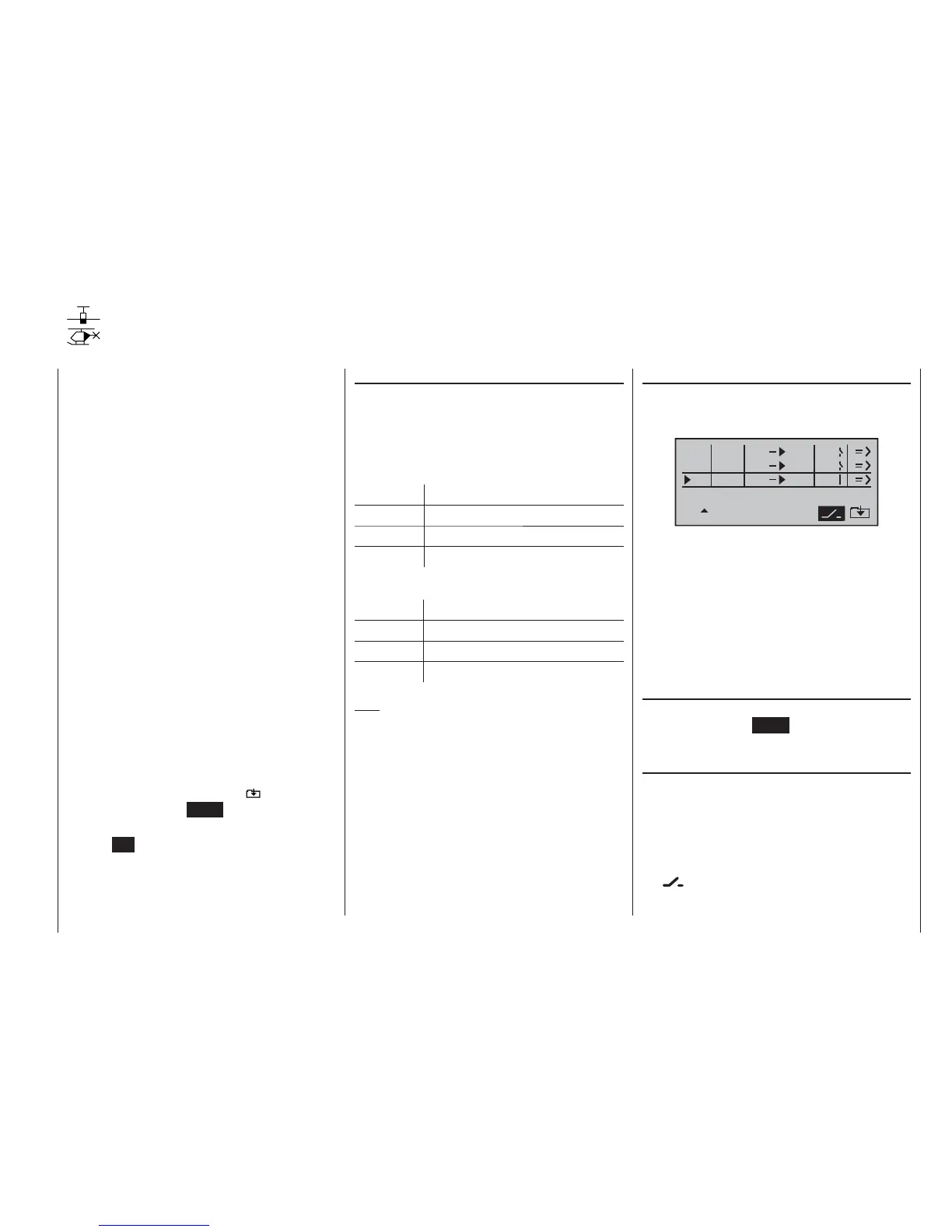
In this example three mixers have already been defi ned.
The second mixer (“Brake ¼ elev”) is already familiar to
us from the »wing mixer« menu. As a general rule you
should always use these pre-programmed mixers fi rst if
possible.
However, if you need asymmetrical mixer ratios on both
sides of centre, or have to offset the mixer neutral point,
then you should set or leave the pre-set mixers at “0”,
and program one of the free mixers instead.
Erasing mixers
If you need to erase a mixer that you have already de-
fi ned, simply press the CLEAR button in the highlighted
fi
eld of the “fro(m)” column.
Mixer switches
In our example above, a physical switch “1” and the
control switch “C1” have been assigned to the two linear
mixers 1 and 2, and switch 3 to mixer 3.
The switch symbol to the right of the switch number
shows the current status of that switch.
Any mixer to which no switch has been assigned in
the
column is permanently switched on.
Regardless of the selected model type, three linear mix-
ers are available for each of the twelve model memories,
with the additional possibility of non-linear characteristic
curves.
In this fi rst section we will concentrate on the program-
ming procedure for the fi rst screen page. We will then
move on to the method of programming mixer ratios, as
found on the second screen page of this menu.
The basic programming procedure
Select mixer 1 ... 3 with the rotary cylinder pressed in.1.
Press the rotary cylinder. The input fi eld “fro(m)” is 2.
highlighted (inverse video).
Defi ne the mixer input “from” using the rotary cylin-3.
der.
Press the rotary cylinder, move to 4. SEL under the “to”
column using the rotary cylinder, and press the rotary
cylinder once more.
The input fi eld “to” is now highlighted.
Defi ne the mixer input “to” using the rotary cylinder.5.
Press the rotary cylinder, and (optionally) move to 6.
SEL under the “type” column using the rotary cylin-
der; you can now include the Ch1 … Ch 4 trim lever
for the mixer input signal (“tr” for trim) …
… and / or move to the switch symbol, press the rota-
ry cylinder again, and assign a switch if desired.
Press the rotary cylinder, move to 7.
using the rota-
ry cylinder, and press ENTER.
Defi ne the mixer ratios on the second screen page.8.
Press 9. ESC to switch back to the fi rst page.
Free mixers
Linear mixers
“fro(m)” column
Press the rotary cylinder, then rotate it to select one of
the control functions 1 … 8 or S in the highlighted fi eld
of the selected mixer line.
In the interests of clarity, the control functions 1 … 4 are
abbreviated as follows when dealing with the fi xed-wing
mixers:
c1 Throttle / airbrake stick
ar Aileron stick
el Elevator stick
rd Rudder stick
… and in the Heli program:
1 Throttle / collective pitch stick
2 Roll stick
3 Pitch-axis stick
4 Tail rotor stick
Note:
Don’t forget to assign a transmitter control to the se-
lected control functions 5 ... 8 in the »contr set.« menu.
“S” for switch channel
The letter “S” (switch channel) in the “from” column has
the effect of passing a constant input signal to the mixer
input, e. g. in order to apply a little extra up-elevator trim
when an aero-tow coupling is closed, as mentioned
earlier.
Once you have assigned a control function or the letter
“S”, an additional SEL fi eld appears in the …