91
Program description: free mixers
MIX 1 6 el off
If this display appears, you have not activated the mixer
b
y operating the assigned external switch – in this case
“1”. To correct this, operate the switch:
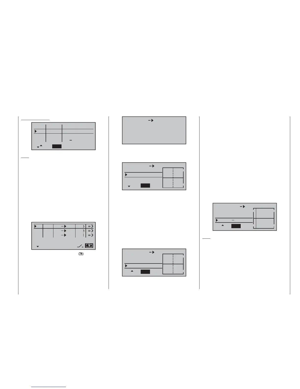
MIX 1 6 el
trv
+
0%
+
0%
0%offs
ASYSYM
The full-height vertical line in the graph represents the
current position of the tr
ansmitter control assigned to in-
put 6. (In the above graph this is located at the left-hand
edge because CTRL 7 is at its left-hand end-point, as
already mentioned.) The full-length horizontal line shows
the mixer ratio, which currently has the value of zero
over the whole stick travel; this means that the elevator
will not “follow” when the fl aps are operated.
The fi rst step is to defi ne the offset (mixer neutral point).
To do this press the rotary cylinder and move to the
“Offs” line:
MIX 1 6 el
trv
+
0%
+
0%
0%offs
ASYSYM
The dotted vertical line indicates the position of the
mix
er neutral point (“offset”), i. e. that point along the
»contr set.« menu
I5
I6
I7
+
trv
100%
100%
100%
100%
100%
100%
SEL
SYM
ASY
empty
ctrl7
empty
++
++
++
Note:
If y
ou assign a transmitter control to input 7 and select
two fl ap servos, input 7 is automatically blocked to avoid
possible malfunctions.
Rotate the transmitter control to its left-hand end-point,
and adjust the landing fl ap linkages so that they are in
the neutral position at this setting. If you now turn the
knob to the right, the fl aps should defl ect down; if they
move up, you must reverse the direction of servo rota-
tion.
Now we turn to the fi rst mixer on the screen on page 89;
this is the mixer “6 ¼ el”, to which switch 1 has been
assigned:
SEL
SEL
typ fro
to
M1
M2
M3
6
c1
S
el
el
el
1
C1
3
Use the rotary cylinder to move to the symbol at bot-
tom right of the screen. Pressing the rotary cylinder now
switches to the second screen page:
control travel at which the mixer has NO infl uence on the
channel connected to its output. By default this point is
set to the centre position.
However, in our example the neutral (retracted) position
of the fl aps is located at the left-hand stop of the rotary
proportional control, and in this position the elevator
must not be affected. We therefore have to shift the mix-
er neutral point exactly to that position. Turn the control
to the left-hand end-stop – if you have not already done
so – and select STO using the rotary cylinder. Press the
rotary cylinder, and the dotted vertical line now moves to
this point – the new mixer neutral point – which always
retains the “OUTPUT” value of zero in accordance with
the mixer defi nition.
As it happens, this setting is diffi cult to show in a
screen shot, so we will change the “offset” value to
only -75%.
MIX 1 6
+
0%
+
0%
75%
CLRSTO
el
trv
offs
Note:
If y
ou wish, you can move the mixer neutral point back
to centre by selecting CLR using the rotary cylinder, and
pressing the rotary cylinder.