101
Program description: Flight phases
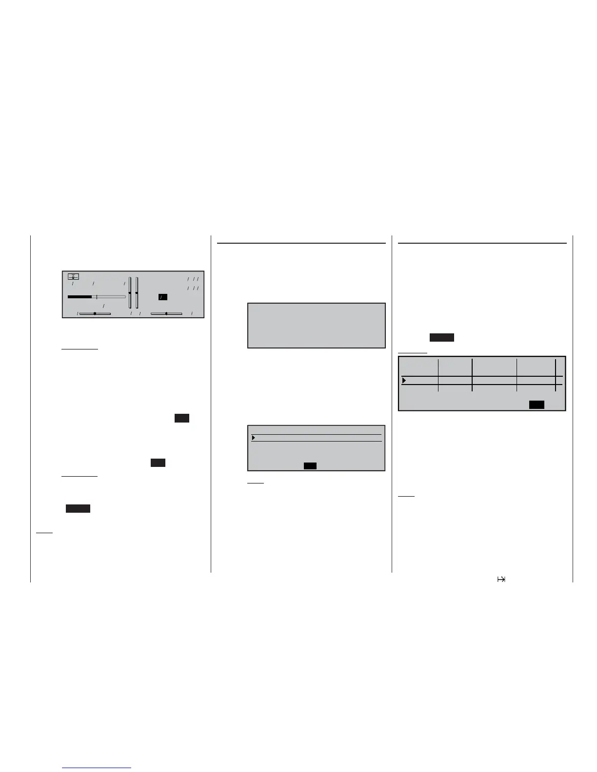
ber of times the switch has been operated.
This counter fi eld appears highlighted when
the switch for the Time1 timer is “open”, i. e.
when the timer is stopped:
DV20KATANA
#03
H-J.Sandbrunner
9.5V
2:30h C62
0000
Stop watch
Flight tim
Time1
«Aerobat»
22.1s
000
000
:
:
02
2:30h SPCM20
If desired, the rotary control can then be used
to read out the sequence of recorded times.
Application:
Typically for recording motor “on” times, assu-
ming that the same switch controls the motor.
Time2 “Time2” records both the “Off” and the “On” ti-
mes of the associated switch, i. e. the timer
restarts every time the switch is operated,
and the counter is incremented by “1”.
You can stop any time count without opera-
ting the switch itself by pressing the ESC but-
ton. Operating the switch in turn increases the
counter by 1, and restarts the Time2 timer.
If you wish to read out the time memory using
the rotary control, you must fi rst halt the
Time2 timer by pressing the ESC button.
Application:
This timer would be used typically to record
the pure gliding times between power pha-
ses, in addition to the motor run times.
Pressing CLEAR at the basic display resets stopped
timers.
Note:
Please note: if you have programmed the “Auto ti-
mer reset” function in the »Base setup model« menu
(see page 64) to “yes”, then these timers are reset
when you switch the transmitter on.
“Motor” column
(see left-hand page if suppressed)
• “yes” The motor connected to receiver output 1
is controlled by the C1 stick (throttle / brake
stick).
The brake system set up in the »Wing mi-
xers« menu is switched off:
BRAKE SETTINGS
off
• “no” The motor connected to receiver output 1 is
de-coupled from the C1 stick (throttle / bra-
ke stick), and is automatically kept at its
OFF position as determined by the “Throttle
min. forward / back” setting.
The brake system set up in the »Wing mi-
xers« menu is switched on, and is cont-
rolled by the C1 stick.
AILE FLAP FL2
Crow
0%
0%
Diff. reduct. 0% 0% 0%
Elevat. curve
0%
=>
BRAKE SETTINGS
Note:
The range of set-up options varies accor-
ding to the number of wing servos selec-
ted in the “Aileron / fl ap” line of the »Model
type« menu.
“Switch time” column
When you switch between fl ight phases, it is advisab-
le to program a “soft” transition INTO (!) the next pha-
se; this is done by entering a transition time in this
column; the range available is 0 to 9.9 seconds. The
mx-24s also allows you to set different transition ti-
mes for switching from, say, Phase 1 to Phase 3, and
from Phase 3 to Phase 1.
After a brief press on the rotary control you can select
a transition time within the range 0 to 9.9 seconds in
the highlighted value fi eld.
(Pressing CLEAR = 0.0 sec)
Example:
Phase 1
Phase 2
3.0s
Phase 3
5.0s
Phase 4
SEL
Normal 4.0s
Launch
0.1s
SEL
-
Landing
+
+
SEL
Name
Fl.ph.Tim.
Sw. time
The set transition time from any other phase into Pha-
se 1 “normal” is 4.0 seconds, but the transition time is
5.0 seconds if you switch from, say, Phase 1 to Pha-
se 3.
Unequal transition times, as shown in our examp-
le, can be useful when switching between widely dif-
fering fl ight phases, such as between aerobatics and
normal fl ight.
Note:
The “transition time” set here applies uniformly to all
fl ight phase specifi c settings, and also to all mixers
activated in the »Wing mixers« menu; see page 110.
This avoids abrupt changes between phase-specifi c
mixers. However, if you wish individual servos to be
switched without delay, simply defi ne them accordin-
gly in the »Non-delayed channels« menu; see page
105.