20
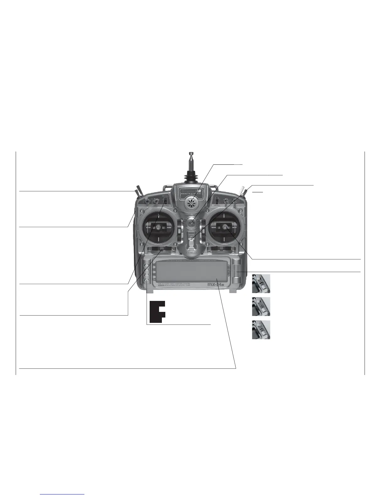
Description of transmitter
Transmitter aerial
(ten-section
telescopic)
Piezo buzzer
Proportional controls
Two proportional controls are mounted on the sides
of the transmitter as standard. A centre detent ensu-
res reproducible centre settings. In this case they are
described in the corresponding menus as : right-hand
control “CTRL 9”, left-hand control “CTRL 10”.
Operating buttons:
ENTER Input button
ESC Back button
CLEAR Erase button
HELP Help button
LCD screen (see page 22 for more details)
The thin protective fi lm over the screen surface can be peeled off using your fi ngers if you wish.
Contrast adjustment: from the basic display press the rotary control and rotate it at the same time; al-
ternatively press the rotary control and press the CONTROL 5 or 6 buttons, if these are not already in
use for other purposes.
Warning indicators : If battery voltage falls below the set threshold • if there is a Trainer system mal-
function • if Channel 1 is too close to full-throttle when the transmitter is switched on • if the Fail-Safe
settings are not correct • power-on warning (checking a switch position).
ON / OFF switch
Note:
Always switch the transmitter on fi rst, followed
by the receiver. After a fl ight: switch the recei-
ver off fi rst, followed by the transmitter.
Rotary control, providing two-level control
Description of transmitter
Front panel
Switches between individual lines within a menu when
held pressed in. When held pressed in turn the rotary
control at the top end of the cylinder for a better grip.
A brief press on the top end of the rotary control chan-
ges the input fi eld, or confi rms your input. Pressing the
HELP button with the rotary control held pressed in
switches directly to the »Servo display« menu from
the basic display and most menus.
If rotated in its normal (non-pressed) state, the rota-
ry control selects your chosen item from the list in the
multi-function menu. Once you have called up a menu
point, the rotary control also changes the entered va-
lue in a highlighted fi eld (light characters on dark back-
ground) which appears at the bottom edge of the
screen. Any alterations you make take effect immedia-
tely. When not pressed in, turn the rotary control at the
bottom end of the cylinder for a better grip.
Transmitter neckstrap lug
Digital trims
For fi ne adjustment of servo (travel neutral) position.
A brief push produces a single increment of offset
(the increment size is variable in the “Stick mode”
menu). The screen displays the trim positions.
Increment / Decrement buttons
Two proportional controls as standard: every time the
button is pressed, the travel of the associated ser-
vo changes by 1% relative to the pre-set servo travel.
INC = positive direction, DEC = negative direction.
These controls are numbered as follows: right-hand
button “CTRL 5”, left-hand button “CTRL 6”. These
two buttons can be used as an alternative to the rota-
ry control if they are not already in use for other pur-
poses.
Stick units
Two dual-axis stick units providing four independent
control functions. Variable-length sticks. The control
functions (i. e. stick mode) can be assigned within the
“Base setup model” menu, e. g. throttle left or right.
The throttle stick can also be set to be self-neutrali-
sing or ratchet action: see page 16.
Switches
Eight external switches as standard (SW = switch), of which
two-position: SW 1, 2, 3, 4, 7, 8 (switch 8: self-neutralising)
three-position: SW 5 + 6, 9 + 10. The three-position switches are
also used as transmitter controls to provide three-position servo tra-
vels. In this case they are described in the corresponding menus as :
right-hand switch “CTRL 7”, left-hand switch “CTRL 8”.