22
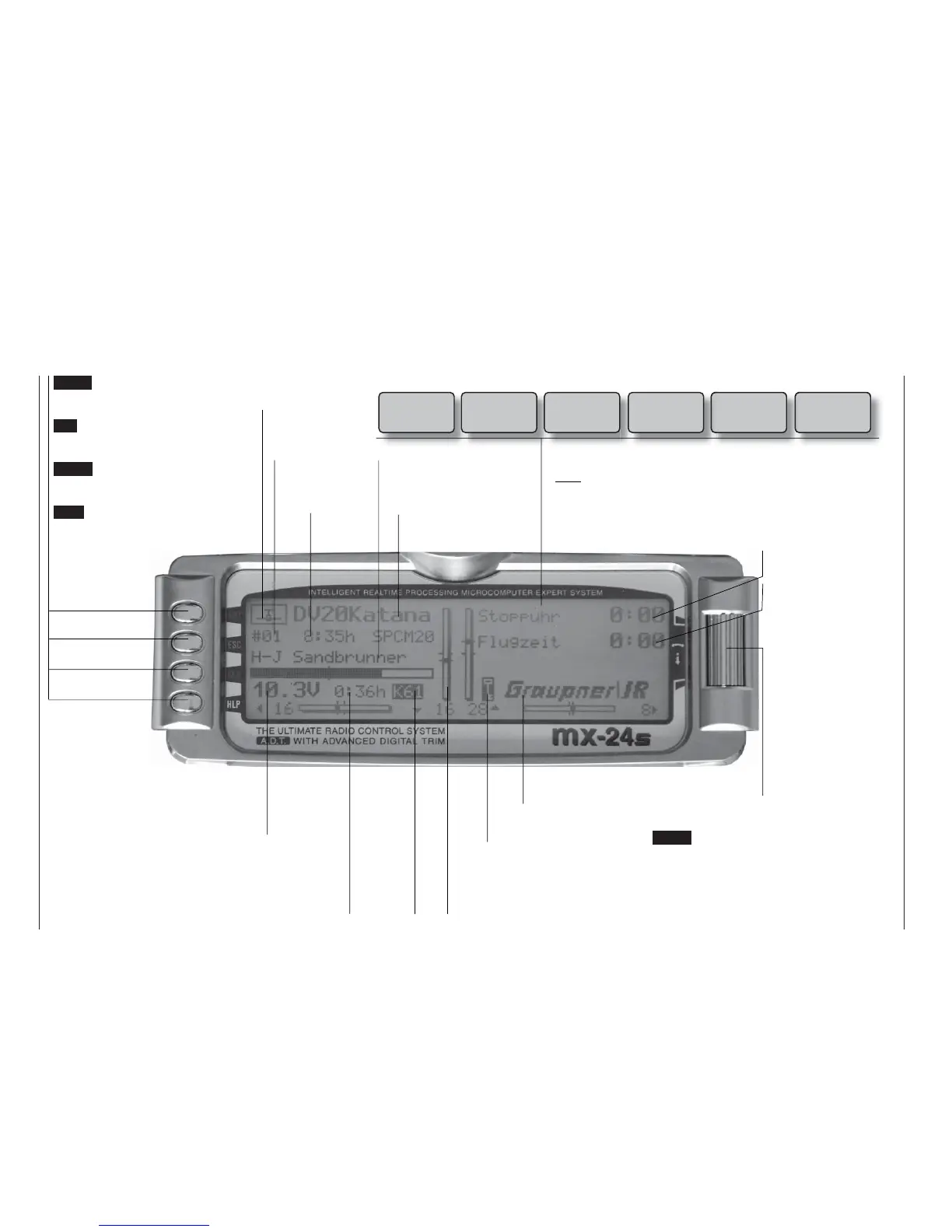
Description of screen
ENTER (Input button):
Switches to multi-function list
Calls up a menu
ESC (Escape button):
Returns step by step from any
menu to the basic display
CLEAR (Erase button):
Resets altered values to default
settings
HELP (Help button):
Calls up a brief help message re-
lating to any menu
Model name
(max. 10 characters)
Model memory
1 … 40
User’s name
(max. 15 characters)
Model ope-
rating time
Superimposed warning messages*
Stopwatch in min:sec
(count-up / count-down)
Flight time in min:sec
(count-up / count-down)
Battery voltage, shown by a dynamic bar
display. If the battery voltage falls below a
particular (selectable) threshold (see page
155), a warning appears on the screen ac-
companied by an audible alert signal.
Transmit-
ter operating
time. This is
automatically
reset to zero
when the bat-
tery is rechar-
ged.
Display diagram for all four digital trim levers with numerical and direction indicators: “
”
or “”. Special cut-off trim for C1 (see page 34).
For each trim lever separately the “shadow” indicates whether the trim operates glo-
bally (= shadow) or separately for each fl ight phase (this parameter is set in the »Stick
mode« menu, see pages 76 / 77). Exception: the C1 trim always operates globally.
The rotary control can be
operated on two levels.
At the basic transmitter
display it is used to ad-
just screen contrast when
held pressed in, or:
Press the rotary control
and adjust screen cont-
rast using CTRL 5 or 6 –
unless these buttons are
already assigned to ano-
ther function.
GRAUPNER logo, alternatively the fl ight pha-
se name. Different fl ight phases are selected
by operating user-assigned switches.
Description of screen
Batt must
be re-
charged!!
Charge battery*
Current
channel
number.
The num-
ber fl as-
hes if the
RF module
is switched
off.
(Note: an additional timer
can also be activated.)
Model type
Fixed-wing or
Helicopter
Notes:
* If the transmitter battery voltage is too low, the message “Currently not possible,
battery voltage too low” appears in the »Model select« and »Copy / Erase« me-
nus.
** For safety reasons this warning can only be disabled for non-powered fi xed-wing
models: in this case select the »Model type« menu (see page 70) and enter
“none” in the “Motor” line.
Unlock by
rotary
and CLR
Button pad lock
Button pad lock
Hold rotary control pressed in + CLEAR button.
Thr
too
high!
Throttle stick too
advanced**
No
pupil
signal
Problem with
Trainer mode
Fail Safe
setup
t.b.d.
Only in PCM20,
SPCM20 and
APCM24 modes
!Warning!
Power-on war-
ning for selectab-
le switch