29
D/R EXPO
D/R EXPO
D/R EXPO
5
6
7
8
9
10
11
12
RF
5
6
7
8
9
10
11
12
1
2
3
4
is possible – and indeed likely – that there will be dif-
ferences between the number of the transmitter con-
trol and the number of the subsequent control chan-
nel.
Control channel
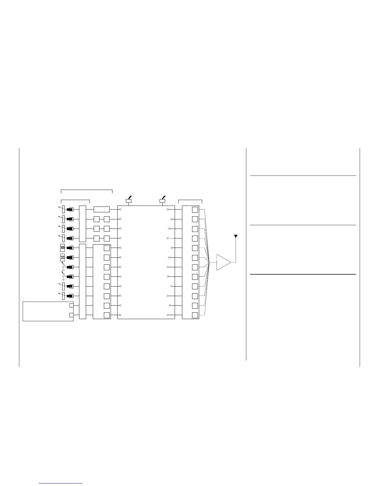
There is a point in the signal path where the signal
contains all the information required to control a par-
ticular servo. Whether it emanates directly from a
transmitter control or indirectly via a mixer, we now
describe this as a control channel. This signal is ge-
nerated individually for each servo, and then leaves
the transmitter via the RF module in order to control
the corresponding servo in the model.
Mixers
The signal fl ow chart includes a wide range of mixer
functions. Their purpose is to enable a control func-
tion to branch at the mixer input, so that it can affect
multiple servos. The mixer programs provided by the
software are extremely wide-ranging and versatile.
Please refer to the section of this manual starting on
page 110, which describes the numerous mixer func-
tions in full detail.
Switches (SW)
Earlier we saw that the two-position and three-po-
sition switches provided by the
mx-24s are able to
move their associated servos to two or three pre-de-
fi ned positions. However, all these switches are also
designed to be used for switching program options,
e. g. for starting and stopping timers, switching mi-
xers on and off, toggling Trainer mode etc.. For this
reason the two three-position switches are also de-
scribed as “SW 5 + 6” and “SW 9 + 10”. The switch
SW 8 – top right, rear – is a self-neutralising unit.
Each switch can be assigned as many functions as
you wish. The linking of several switches in “AND”
or “OR” combinations (see the »Logical switches«
menu on page 97) enables them to be used in very
complex superimposed arrangements. Numerous ex-
amples are described later in this manual.
Defi nition of terms
Control function
Control channel
Aerial
Servo adjustment: reverse - centre - travel - limit
mx-24s-Programme
For example:
Model type
Helicopter type
Control switches
Logical switches
Phase settings
Phase assignment
Non-delayed channels
Wing mixers
Helicopter mixers
Free mixers
MIX active in phase
MIX only channel
Dual mixers
2-position switch
3-position switch
For switching mixers, auto-
rotation, fl ight phases etc.
Function input
Channel 1
curve
Dual-axis stick unit
Dual-axis stick unit
Transmitter control
(digital button) 5
Transmitter control
(digital button) 6
Transmitter control 7
(3-position switch)
Transmitter control 8
(3-position switch)
Transmitter control 9
(right-hand side-mounted
rotary control)
Free assignment of
transmitter controls 1,
5 … 10 and of all swit-
ches (SW) by software
Stick mode 1 … 4Unrestricted transmitter control assignment, inputs 5 … 12
Transmitter control settings: offset - control travel - time
Transmitter controls
By default transmitter controls
5 …12 are de-coupled in the
software – (exception:
Throttle limiter control)
Transmitter control inputs 1 …
4 can be interchanged in the
»Base setup model« menu.
Transmitter controls 1 and 5
… 10 can be assigned to in-
puts 5 … 12 in any order in
the »Control adjust« menu.
Mixer input
Mixer output
Transmitter control 10
(left-hand side-mounted
rotary control)
Signal fl ow chart
or