189
Programming examples: Fixed-wing model
can result in unwanted moments which are very diffi -
cult to correct.
Delta / Flying wing of the “2 AIL 1 / 2 / 4 FL” type
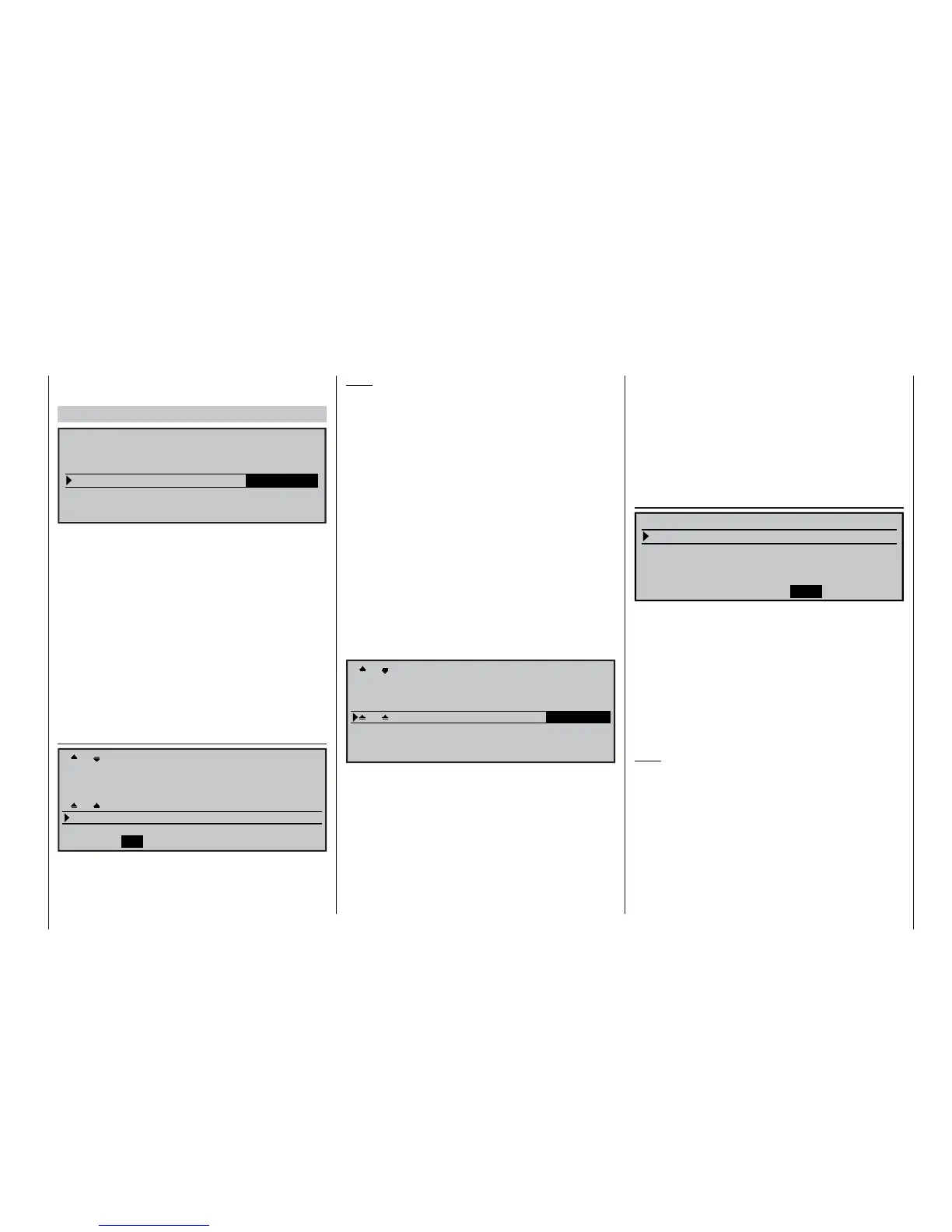
SEL
Offset +100%
2 AIL 4 FL
Delt/fl.wing
MODELTYPE
Tail type
Aileron/camber flaps
Brake
Input 1
Motor on C1 None
In the case of deltas and fl ying wings with more than
two wing fl aps it is possible to compensate for unwan-
ted moments more easily. For example, the “tipping”
moment (= up-elevator effect) when ailerons are de-
fl ected up can be corrected by lowering the fl aps (=
down-elevator effect) to the appropriate degree.
If you decide on a model of this type and have con-
nected the servos to the receiver sockets as stated
in the table above, then the aileron function will work
correctly for the two (outboard) aileron servos, but
the elevator function of the two aileron servos and – if
present – the (inboard) fl aps will not.
This is only achieved when you select “2AIL 1 / 2 / 4
FL” in the “Multi-fl ap menu” of the menu …
»Wing mixers« (page 110)
+100% +60%
+30%
+60% +30%
Diff. 0% 0%
0%
0% 0%
0% +100%
SYM
+100%
0%
0%
ASY
SYM
ASY
ASY
+100% +100%+100%
SYM
0% 0%
0%
0%
0%
0%
AILE
FLAP FL2
AI
Ail–tr
Fl.pos
FL
El–
>
Fl
… where you set up the effect of the elevator control
system on ailerons, fl aps and – if present – fl aps 2 in
the “El->Fl” line.
Note:
Aileron trim can be set separately (see below), but
the trim is transferred together with the set mixer va-
lue if the “El->Fl” mixer is employed.
The following settings vary widely from model to
model. Please do not assume that the stated va-
lues will be correct for your particular design!
In the top line of this “Multi-fl ap menu” we can set the
effect of the aileron stick on ailerons, fl aps and – if
present – FL2, in a similar manner to a “normal” four-
fl ap or six-fl ap wing. However, the effect of the aileron
trim on ailerons and fl aps is set in the “Ail-tr” line be-
low it.
The setting for differential travel is rather a delica-
te matter with this model type; we recommend that
you do not set a value for differential at all unless you
have considerable experience with this model type.
In the interests of safety, in the “
FL
” line you
should change the default value of 100% in the
“FLAP” column – and of “FL2” if present – to 0%:
+100% +60%
+30%
+60% +30%
Diff. 0% 0%
0%
0% 0%
0% 0%
+55% +55% +55% +55%
SYM
+100%
0%
0%
+55%
+55%
ASY
SYM
ASY
ASY
0%
SYM
AILE
FLAP FL2
0% 0%
AI
Ail–tr
Fl.pos
FL
El–
>
Fl
In the »Transmitter control adjust« menu the de-
fault setting for all inputs is “free”, which is perfectly
safe. However, if you should assign a transmitter con-
trol in error at a later date, this setting will at least pre-
vent it having an unwanted effect.
We have already discussed the last line – “El->Fl” – in
the previous section.
Many years ago the author operated a model delta
using the mc-20 of the period, programmed (in prin-
ciple) exactly in this way, with the refi nement of a but-
terfl y (crow) landing aid – the latter exploiting the
“Brake aileron” and “Brake fl ap” wing mixers to
provide complete automatic compensation for pitch
trim changes. In this case the term “ailerons” means
the outboard wing control surfaces, and “fl ap” the in-
board pair of control surfaces.
To achieve this with the
mx-24s you should move to
the “Brake settings” menu of the menu …
»Wing mixers« (page 110)
FL2
–50%
0%
0% 0% 0%
=>
+60%
FLAP
AILE
Crow
BRAKE SETTINGS
Elevat. curve
Diff. reduct.
… and enter appropriate values in the “Crow” line for
the ailerons (to be raised) and the “fl aps” (to be lowe-
red), then carry out adjustments so that the unwanted
pitching moments cancel each other out, i. e. the mo-
del maintains a stable attitude. However, you must be
careful to allow the wing fl aps suffi cient “scope” to act
as elevators, i. e. do not use the whole of the servo
travel for the crow settings alone.
You can safely ignore all the other settings in this
menu.
Note:
The “Brake settings” menu is switched “off” if you en-
tered “Motor on C1 forward / back” in the »Model
type« menu (see page 70), and leave “yes” for the
currently active fl ight phase in the “Motor” column of
the »Phase settings« menu (see page 100). You may
therefore need to switch fl ight phases.
A modern sweptback fl ying wing can be operated in
a similar way. Many of these models also feature in-
board and outboard control surfaces: the former for-
ward of the Centre of Gravity, the latter aft of it. De-