26
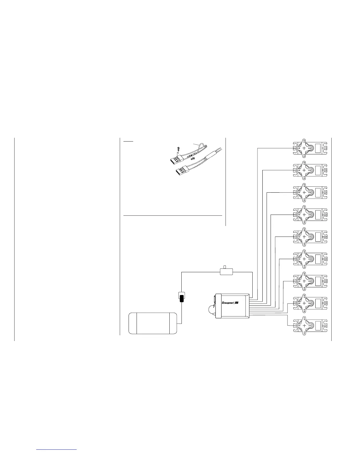
Batt.
Servos
1
2345678 9
Installation notes
Note:
If you wish to use a re-
ceiver battery and a
speed controller with
integral BEC* system
simultaneously, it is
usually necessary to
disconnect the positi-
ve (red) wire from the
3-pin plug. This varies from controller to controller, so
please read the instructions supplied with the unit.
Use a small screwdriver carefully to raise the centre
lug of the plug (1), withdraw the red wire (2) and wrap
the exposed contact with insulating tape to prevent
possible short-circuits (3).
*Battery Elimination Circuit
Please read the installation notes relating to the re-
ceiver, the receiver aerial, and the servos on the follo-
wing page.
If the receiver is of the type requiring an interchange-
able plug-in crystal, the channel number of the recei-
ver must be identical to the channel number set on
the transmitter. In this case it is only permissible to
use the plug-in crystals marked “R” (for Receiver) as
shown in the table on page 206. No receiver crystal
is required if you are using a GRAUPNER PLL Syn-
thesizer receiver. According to the receiver type, the
desired channel number is set either directly on the
receiver using the channel selector, or by means of a
frequency scan; see the instructions supplied with the
receiver.
GRAUPNER receivers are fi tted with polarised so-
ckets, so that the servos and power supply cannot be
connected the wrong way round; you will fi nd that the
plugs are slightly chamfered on one edge to match
the sockets. Connect the battery to an ON / OFF
switch harness (see the main GRAUPNER FS cata-
logue), and connect the switch to the socket on the
receiver marked “Batt”.
If you use the DS 24 FM S or amc24DSCAN recei-
ver you can control up to twelve servos, speed cont-
rollers etc. directly. Servos 1 to 12 can be controlled
using the two dual-axis sticks and – after appropria-
te programming – any other (proportional) controls or
switches present on the
mx-24s transmitter. The two
latter types of controls can be assigned to inputs 5 …
12 in the software; see the »Transmitter control ad-
just« menu, pages 78 / 80. However, all servos can
also be accessed via mixer functions; see the »Free
mixers« menu on page 135.
1
2
3
red
Receiving system
(not included in the set)