43
Model helicopters
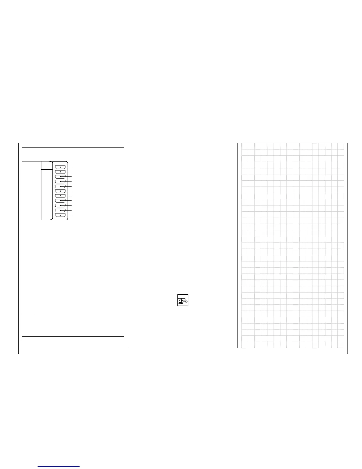
Receiver socket sequence:
The servos MUST be connected to the receiver out-
put sockets in the following sequence:
Outputs not required should simply be left unused.
For more details on the different types of swashplate
please refer to the »Helicopter type« menu descri-
bed on page 72.
If you are using a PPM-FM receiver made by ano-
ther manufacturer* in a model which was previously
fl own using a non-Graupner transmitter, and you wish
to operate it with a GRAUPNER transmitter, e. g. the
mx-24s for Trainer mode operations, it may be ne-
cessary to re-connect servos to the outputs in the or-
der stated earlier. Alternatively you can carry out the
adjustments in the »Receiver output swap« menu,
see page 153. You may also need to adjust servo tra-
vels and directions of rotation; these adjustments are
always carried out in the »Servo adjustment« menu;
see page 74.
Notes:
• Compared with the receiver channel sequence of
earlier GRAUPNER radio control systems, servo
socket 1 (collective pitch servo) and servo socket
6 (throttle servo) have been interchanged.
• If you are using the
mx-24s but do not want to
abandon separate collective pitch trim, you will
need to set up a suitable mixer in the »Free mi-
xers« menu, e. g. an 8 1 mixer, and program
a symmetrical mixer input of around 25%. Now
move to the »Transmitter control adjust« menu
and assign the left-hand side-mounted proportio-
nal control CTRL 10 (still free as standard) to mi-
xer input “8”; alternatively you could assign one
of the two INC / DEC buttons CTRL 5 or 6, if the-
se controls are not already in use for other purpo-
ses. The advantage of the latter is that their set-
tings are stored separately for each fl ight phase;
see also page 28.
However, in the interests of safety we also recom-
mend that you de-couple the assigned transmit-
ter control from input 8 in the »Mix only channel«
menu, so that the same transmitter control cannot
also operate a servo connected to receiver output
8. See also Example 3 on page 141.
Different methods of installing servos and control lin-
kages may make it necessary to reverse the direction
of rotation of some servos when programming. You
can correct this by using the servo reverse facility lo-
cated in the »Servo adjustment« menu, see page
74.
In the “Program descriptions” all menus which are re-
levant to model helicopters are marked with a “heli-
copter” symbol:
This means that you can easily skip irrelevant menus
when programming a model helicopter.
* GRAUPNER does not guarantee that GRAUPNER radio cont-
rol systems will work correctly in conjunction with receiving sys-
tems and radio control equipment made by other manufacturers.
Battery
Free, or speed governor
Free, or gyro gain
Motor speed (throttle servo or speed controller)
Free, or pitch-axis (2) servo (4-point linkage)
Tail rotor servo (gyro system)
Pitch-axis (1) servo
Roll (1) servo
Collective pitch or roll (2) or
pitch-axis servo (2) servo
Batt
9
8
7
6
5
4
3
2
1
10
Free, or aux. function
Free, or aux. function
Receiver