103103
Program description:
Flight phases
Application:
Typically for recording phases of fl ight with
increased motor speed, assuming that the
same switch is used to move between pha-
ses.
Time2 “Time2” records both the “Off” and the “On” ti-
mes of the associated switch, i. e. the timer
restarts every time the switch is operated,
and the counter is incremented by “1”.
You can stop any time count without opera-
ting the switch itself by pressing the ESC but-
ton. Operating the switch in turn increases the
counter by 1, and restarts the Time2 timer.
If you wish to read out the time memory using
the rotary control, you must fi rst halt the
Time2 timer by pressing the ESC button.
Application:
This timer would be used typically to record
the time required to complete fl ight tasks
which follow immediately after one another.
Pressing CLEAR at the basic display resets stopped
timers.
Note:
Please note: if you have programmed the “Auto ti-
mer reset” function in the »Base setup model« menu
(see page 64) to “yes”, then these timers are reset
when you switch the transmitter on.
“Switch time” column
When you switch between fl ight phases, it is advisab-
le to program a “soft” transition INTO (!) the next pha-
se; this is done by entering a transition time in this
column; the range available is 0 to 9.9 seconds. The
mx-24s also allows you to set different transition ti-
mes for switching from any of phases 1 … 7 to, say,
phase 3, than for into Phase 1.
However, for safety reasons there is ALWAYS zero
delay when switching into the auto-rotation fl ight pha-
se. The arrow “” in the “Transition time” column in-
dicates that a delay time can be selected OUT OF (!)
auto-rotation INTO (!) another phase.
After a brief press on the rotary control you can select
a transition time within the range 0 to 9.9 seconds in
the highlighted value fi eld.
(Pressing CLEAR = 0.0 s.)
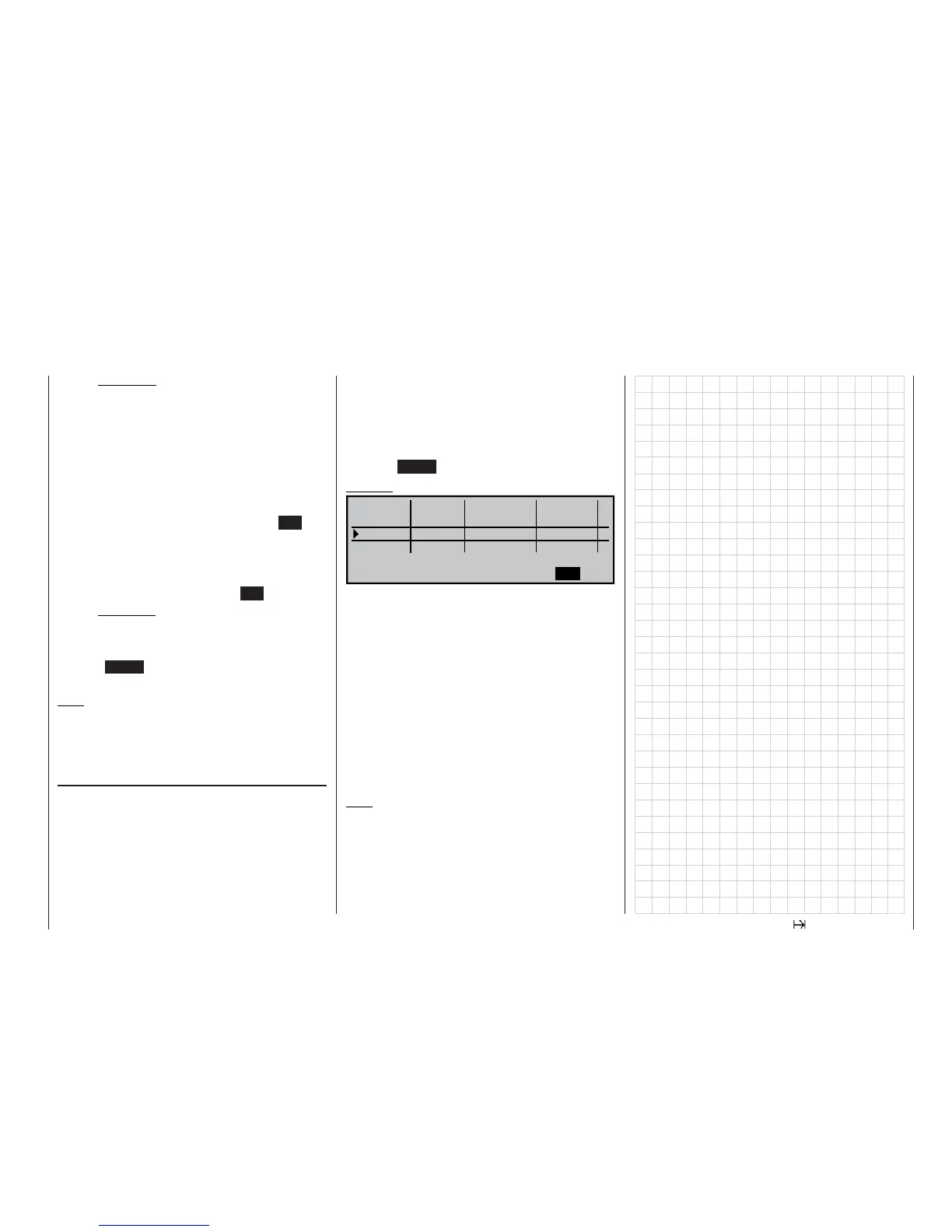
Example:
Autorot
Phase 1
3.0s
Phase 2
1.0s
Phase 3
SEL
Autorot 2.0s
Normal
0.1s
SEL
-
Aerobat
+
+
SEL
–
Name
Fl.ph.Tim. Sw. time
“Autorot”: the set transition time from this phase
into any other phase is 2.0 seconds. In
the reverse direction the transition time
is always 0.0 seconds.
“Phase 1”: the transition time into this phase from
any of the phases 2 … 7 is 3.0 seconds,
i. e. a smooth transition.
“Phase2”: the transition time into this phase from
any of the phases 1 or 3 … 7 is 1.0 se-
conds.
Unequal transition times, as shown in our examp-
le, can be useful when switching between widely dif-
fering fl ight phases, such as between aerobatics and
normal fl ight.
Note:
The “transition time” set here applies uniformly to
all fl ight phase specifi c settings, and also to all mi-
xers activated in the »Helicopter mixers« menu; see
page 122. This avoids abrupt changes between pha-
se-specifi c mixers. However, if you wish individu-
al servos to be switched without delay, simply defi -
ne them accordingly in the »Non-delayed channels«
menu; see page 105.