105
Program description: Flight phases
• Please check the switch assignments carefully;
ensure in particular that you have not already as-
signed a particular switch to another function acci-
dentally.
Important note:
The model settings you entered before you assi-
gned the phase switches are now stored in the
“1 Normal” fl ight phase, i. e. all fl ight phase spe-
cifi c menus are reset to the default values in the
other fl ight phases.
You can replace these default settings with the
data from the “normal” fl ight phase, which you
have, of course, already checked and correc-
ted by test-fl ying. This is accomplished using the
“Copy fl ight phase” command in the »Copy / Era-
se« menu; the data can then be modifi ed in the
new fl ight phases as required. This avoids the ne-
cessity of programming each fl ight phase “from
the ground up”.
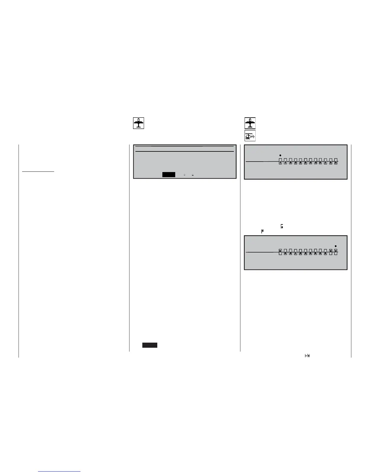
NONDELAYED CHANNELS
non-delayed
normal
135791112
«Normal »
246810
In the »Phase settings« menu you have (presumab-
ly) set up transition times for the shift from one fl ight
phase to another. In this menu you can switch the de-
lay off again for particular channels, e. g. to activate or
disable motor-cut with electric models, heading lock
for helicopter gyros etc..
Use the rotary control to move the “” symbol to the
corresponding channel, then press the rotary control.
The switch symbol changes from “normal” to “non-
delayed” , and vice versa.
135791112
«Normal »
246810
NONDELAYED CHANNELS
non-delayed
normal
Non-delayed chan
Channel-specifi c fl ight phase delay
Phase trim F3B
Flight phase specifi c wing fl ap settings
Normal
Launch 0%
Landing 0%
«Normal » ELEV
FL2
FLAP
AI
0%
0% 0% 0%
0% 0% 0%
0% 0% 0%
This menu provides a phase specifi c trim setting fa-
cility for a minimum of just ELEV, and a maximum of
ELEV, AI, FLAP and FL2, i. e. up to four control func-
tions, according to the settings entered in the “Ai-
lerons / fl aps” line of the »Model type« menu (see
page 70).
“ELEV” column
In this column you can set an elevator
trim value which is to be stored separa-
tely for each fl ight phase.
“AI”, “FLAP”, “FL2” column
The values in these columns are iden-
tical to those in the “Fl.pos” (fl ap posi-
tion) line of the “Multi-fl ap menu” within
the »Wing mixers« menu. For this re-
ason any changes always affect the
other menu immediately.
The position of the fl ight phase switches, which were
earlier defi ned in the »Phase assignment« menu
(see left-hand page), determines which line is selec-
ted and marked with an asterisk (*) at the left-hand
end. At the same time the name of the corresponding
fl ight phase is superimposed in the bottom left-hand
corner of the screen. You can only enter settings for
the currently active fl ight phase.
Select the appropriate column using the rotary cont-
rol, press the rotary control briefl y, then use the rota-
ry control or (if applicable) one of the two INC / DEC
buttons to set the required values independently of
each other, within the range -125% to +125% (pres-
sing CLEAR = 0%).