113
Program description: Mixers
while pressing CLEAR resets the value to 0%.
This setting can only be carried out symmetrically re-
lative to the neutral point of the aileron stick.
A value of around 50% is generally an excellent star-
ting point.
Model type: “1 AIL 1 FL”
If you enter “1 AIL 1 FL” in the “Ailerons / fl aps”
line of the »Model type« menu (see page 70), the
transmitter’s “Wing mixer menu” will look similar to the
screen-shot below:
Brake settings
Aileron
=>
2–
>
4
rudder
0%
Flaps
6–
>
3 elevator 0% 0%
Elevator
3–
>
6 flaps 0% 0%
WING MIXERS
A brief press on the rotary control from the fi rst line of
this page takes you to the following sub-menu …
Brake settings
Note:
The “Brake settings” menu is switched “off” if you en-
tered “Motor on C1 forward / back” in the »Model
type« menu (see page 70), and leave “yes” for the
currently active fl ight phase in the “Motor” column of
the »Phase settings« menu (see page 100). You may
therefore need to switch fl ight phases:
Crow
FLAP
BRAKE SETTINGS
Elevat. curve
=>
0%
With the selected model type you can now enter a
suitable value in the “Butterfl y” line in order to lower
the fl aps when you operate the brake control, which is
generally the C1 stick.
To set up this function, fi rst move the brake control to
its “brake” end-point, press the rotary control briefl y,
then set a suitable value. To obtain an adequate bra-
king effect you should lower the fl aps as far as pos-
sible, i. e. to the limit set by the mechanical linkage.
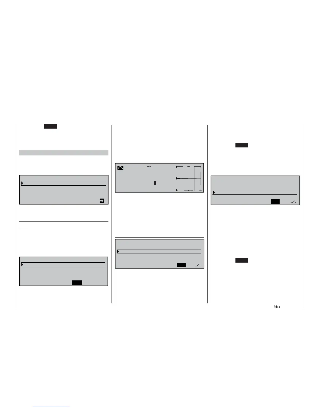
A brief press on the rotary control takes you from this
screen page to the “Elevat. curve” sub-menu:
Brake
Input
+50
%
Output 0%
off
m
OUTPUT
--
+
100
Elevator
Point ?
Curve
If you have the feeling after the fi rst fl ight that you al-
ways needed to use up-elevator to compensate for a
pitch trim change when the airbrakes were extended,
you can program an automatic elevator mixer at this
point.
For details on setting up a curve mixer please refer to
page 90, where the »Channel 1 curve« mixer is dis-
cussed.
Aileron 2 4 rudder
SEL
Brake settings
Aileron
=>
2–
>
4 rudder 0%
Flaps
6–
>
3 elevator 0% 0%
Elevator
3–
>
6 flaps 0% 0%
WING MIXERS
This mixer causes the rudder to “follow” automatically
when an aileron command is given.
Select the SEL fi eld, and give the rotary control a
brief press. You can now set the desired value for this
function using the rotary control. The mixer direction
must be selected to ensure that the rudder moves in
the same direction as the up-going aileron.
If you assign a switch to this function in the right-hand
column, you will be able to switch the mixer on and off
in fl ight.
The available range of values is -150% to +150%,
while pressing CLEAR resets the value to 0%.
This setting can only be carried out symmetrically re-
lative to the neutral point of the aileron stick.
A value of around 50% is generally an excellent star-
ting point.
Elevator 3 6 fl aps
SYM
ASY
Brake settings
Aileron
=>
2–
>
4 rudder 0%
Flaps
6–
>
3 elevator 0% 0%
Elevator
3–
>
6 flaps 0% 0%
WING MIXERS
This mixer causes the fl aps to defl ect when an ele-
vator command is given. The mixer direction must be
selected to ensure that up-elevator causes a down-
fl ap defl ection, and down-elevator causes up-fl ap.
Set up in this way, the fl aps support the effect of the
elevator, making the model more agile around the la-
teral (pitch) axis.
Select SYM in order to set symmetrical travels for up-
and down-elevator, or ASY for different travels either
side of neutral.
The available range of values is -150% to +150%,
while pressing CLEAR resets the value to 0%.
If you assign a switch to this function in the right-hand
column, you will be able to switch the mixer on and off
in fl ight.
The “usual” values for this mixer are in the low two-di-
git range.