118
makes it possible to set the correct direction of diffe-
rential regardless of the direction of rotation of the ai-
leron servos.
Pressing CLEAR resets differential to the default va-
lues.
“Fl.pos” (camber-changing fl ap position)
+100% 0% 0%
0%
0%
0% 0%
0%
0% 0%
0% +100%+100%
0% 0% 0%
0%
SEL
SEL SEL
+100%
0%
+100%+100%
0%
0%
0%
FL2
AILE
FLAP
AI
Ail–tr
Diff.
Fl.pos
FL
El–
>
Fl
At this point you can set up the camber-changing
fl ap positions for all the wing fl aps, separately for
each fl ight phase, i. e. you can determine the positi-
on which the fl aps take up when you select each fl ight
phase. Settings in this line also take effect immediate-
ly in the »Phase trim F3B« menu, as both menus are
based on the same data sets.
The adjustment range of -100% to +100% makes it
possible to set the correct direction of travel regard-
less of the direction of rotation of the aileron and fl ap
servos.
Note:
If you use one or multiple transmitter controls in the
various fl ight phases, as described in the explanation
which follows this section, then these controls also in-
terpret the FL positions set at this point as the offset
and centre positions. If you are familiar with the fl ight
phase specifi c offset shift in the »Transmitter cont-
rol adjust« (see page 78) as used in the mc / mx-
22(s), please note that this is NOT necessary with the
mx-24s.
118
Program description: Mixers
“Fl” (Effect of the fl ap control)
In this line you select SYM or ASY in order to deter-
mine the extent in percentage terms to which the set-
tings of Input 6, carried out in the »Transmitter cont-
rol adjust« menu (see page 78), are to affect the fl ap
settings of the ailerons and fl aps.
+100% 0% 0%
0%
0%
0% 0%
0%
0% 0%
0% +100%+100%
0% 0% 0%
0%
SYM
+100%
0%
+100%+100%
0%
0%
0%
ASY
SYM
ASY
SYM
ASY
FL2
AILE
FLAP
AI
Ail–tr
Diff.
Fl.pos
FL
El–
>
Fl
For each pair of wing fl aps it is possible to defi ne a
symmetrical or asymmetrical effect. Activate the SYM
or ASY fi eld as required. (If you have left the travel
settings at +100% in each case in the »Transmit-
ter control adjust« menu (see page 78), then values
within the range 5 to 20% should generally be suffi -
cient at this point.)
Please see the note under the heading “Fl.pos” for in-
formation on setting offsets.
Pressing CLEAR resets altered entries to the stan-
dard values of +100% for the two pairs of fl aps, and
0% for the aileron pair.
Note:
By default NO transmitter control is assigned to In-
put 6. However, you can assign a transmitter control
or switch to this input at any time, and thereby set dif-
ferent fl ap settings within a fl ight phase; see also ex-
ample 2 on page 180.
“El Fl” (Elevator fl ap)
This mixer causes the fl aps and ailerons to defl ect
when an elevator command is given. The mixer direc-
tion must be selected to ensure that up-elevator cau-
ses a down-fl ap defl ection, and down-elevator causes
to which the aileron trim is to affect “AILE”, “FLAP”
and – if present – “FL2”.
The available range of values is -150% to +150%, re-
lative to the adjustment range of the trim lever.
Pressing CLEAR resets altered entries to the default
values, as shown in the screen-shot shown above.
“Diff.” (Differential aileron function)
If “2 AIL 1 FL” is selected, this is found one level hig-
her in the »Wing mixers« menu; see the screen-shot
at top left on the previous double page.
+100% 0% 0%
0%
0%
0% 0%
0%
0% 0%
0% +100%+100%
0% 0% 0%
0%
SEL
SEL SEL
+100%
0%
+100%+100%
0%
0%
0%
FL2
AILE
FLAP
AI
Ail–tr
Diff.
Fl.pos
FL
El–
>
Fl
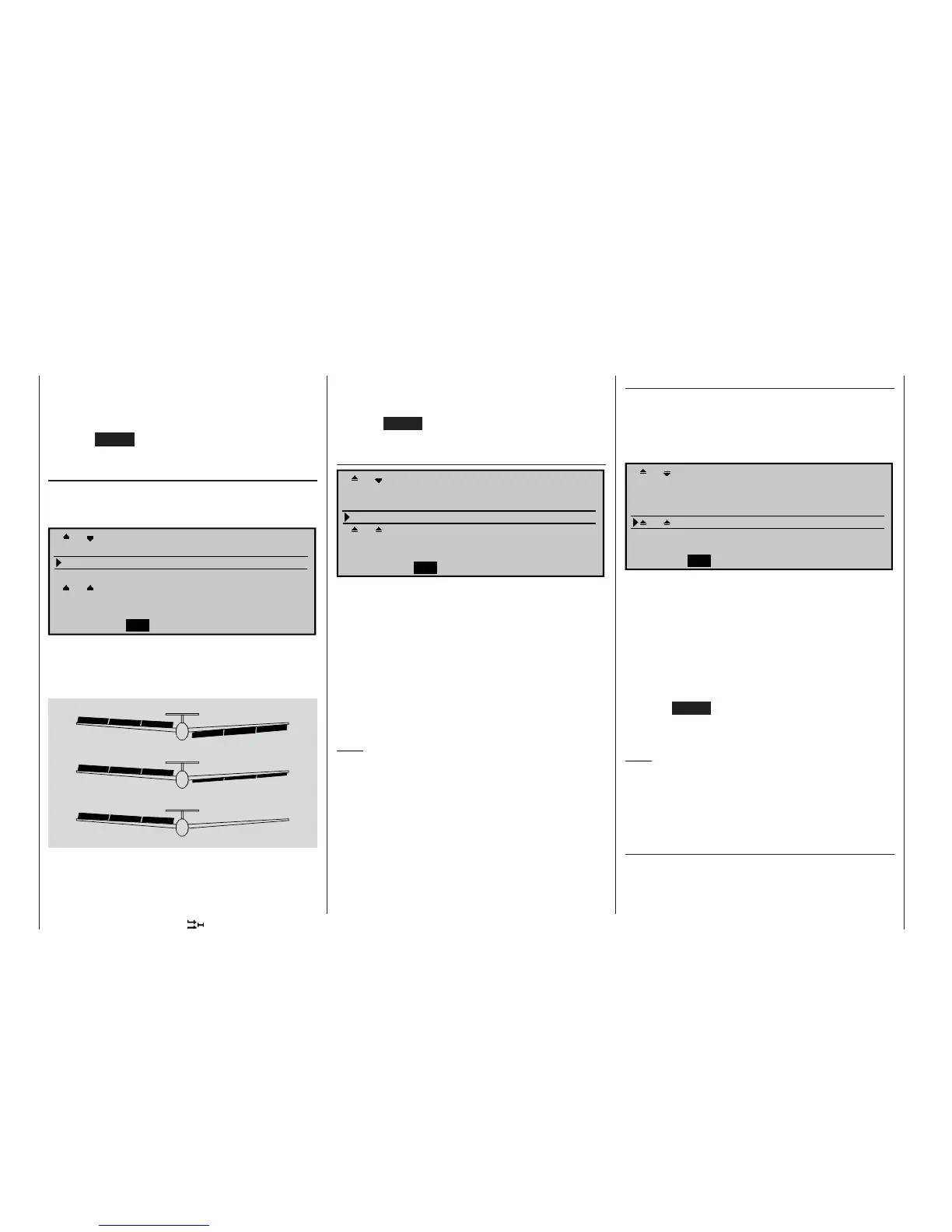
In this line you can set the differential travel of the ai-
lerons, and also of the fl aps FLAP and – if present –
FL2, assuming that you wish the latter to operate as
superimposed ailerons.
0% (Normal)
50% (Differential)
100% (Split)
AIL
FL
FL2
FL2
FL
AIL
If you are not clear about the meaning of aileron diffe-
rential, please read the explanation at the start of this
section on page 111.
The available adjustment range of -100% to +100%