120120
Program description:
Mixers
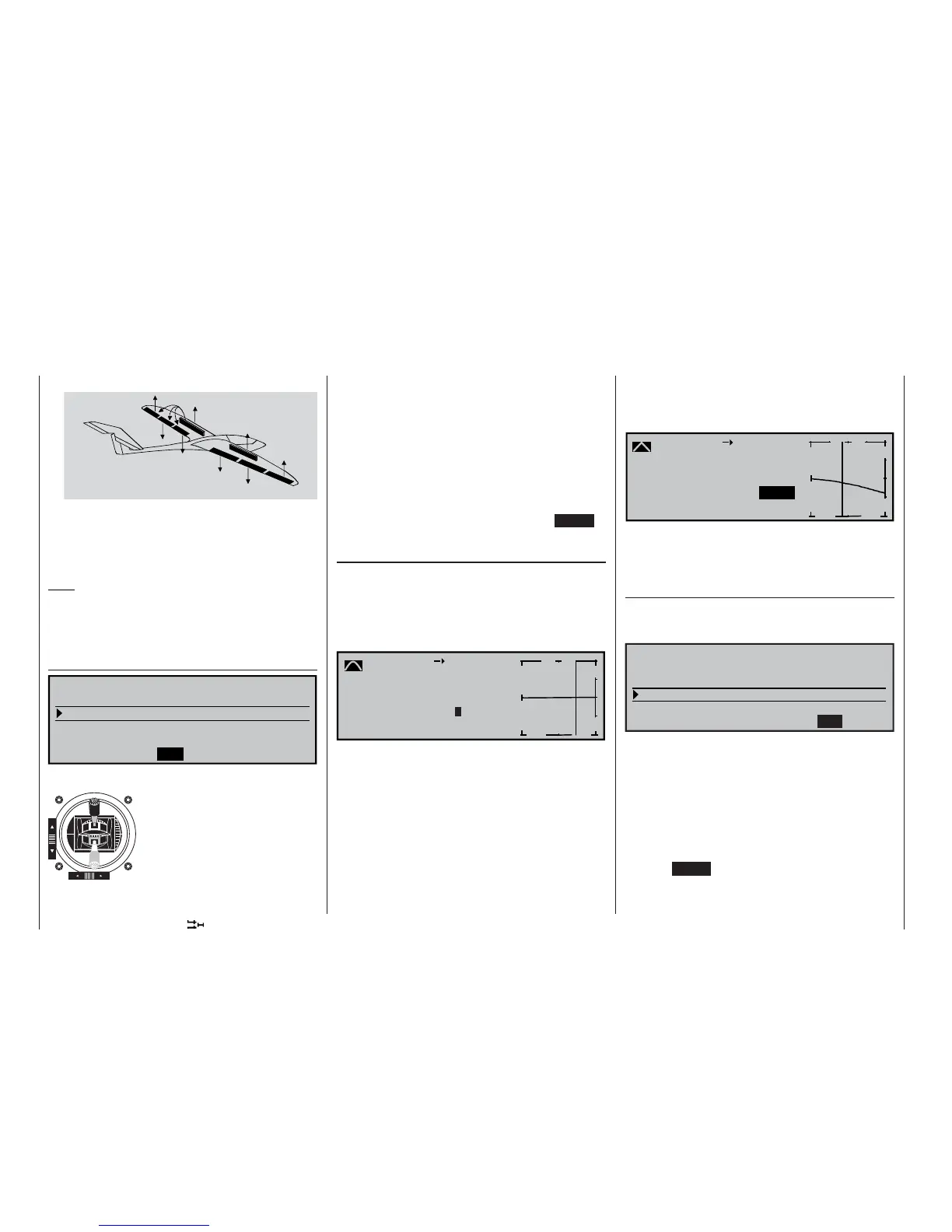
c) Combination of AIL and FL : “Butterfl y” (Crow)
AILE
FLAP
FL2
FL2
FLAP
AILE
In the butterfl y setting (also known as “crow” bra-
king) both ailerons defl ect up as already descri-
bed, and all the camber-changing fl aps defl ect
down as far as possible. This brake setting provi-
des glide path control on the landing approach.
Note:
When any of the mixer confi gurations (a … c) are de-
ployed, and when conventional airbrakes are exten-
ded, it is usually necessary to correct the glide angle
using the “Elev. curve” mixer described on the right.
“Diff. redukt.” (differential reduction)
0%
0%
0% 0% 0%
=>
0%
AILE FLAP FL2
Crow
Diff. reduct.
Elevat. curve
BRAKE SETTINGS
Differential travel can be set for
all three pairs of wing fl aps, as
described earlier in the multi-
fl ap menu. However, when an
extreme butterfl y (crow) setting
is selected, response to aileron
commands tends to be serious-
ly reduced (see page 114 for an
example). To overcome this pro-
blem this mixer is used to sup-
press the degree of aileron differential (set in the mul-
ti-fl ap menu) to an increasing extent as the brakes
are progressively deployed.
A value of 0% means that the “Aileron differential”
set at the transmitter remains fully in force. An entry
the same as the set %-value of the aileron differenti-
al means that the differential is completely eliminated
when the butterfl y (crow) function is at maximum tra-
vel, i. e. when the fl aps are fully extended. Setting a
reduction value greater than the set aileron differenti-
al causes “reverse” differential.
The adjustment range is +/-150%; pressing CLEAR
= 0%.
“Elev. curve” (Brake elevator)
If the airbrake control – assigned to 1, 7, 8 or 9 in the
»Model type« menu (see page 71) – is used to ex-
tend the fl aps as already described in the “Brake set-
tings” menu, a pitch trim (elevator) correction is gene-
rally needed. A brief press of the rotary control takes
you on to the following screen:
Brake
Input
+50
%
Output 0%
off
m
OUTPUT
--
+
100
Elevator
Point ?
Curve
Set-up notes for the Elev. curve (Brake EL)
The offset which you have already set in the »Model
type« menu (see page 70) affects this mixer in the
following way:
The vertical line in the display, which indicates the po-
sition of the airbrake control, only moves away from
the edge of the graph when the set offset is excee-
ded. The airbrake control travel is automatically ex-
panded back to 100%, as described in the »Model
type« menu.
The neutral point of the elevator mixer therefore al-
ways remains at the left-hand margin, regardless of
“forward”
Brake retracted
“back”
Brake extended
the offset you have selected.
Now adjust the Elev. curve in the direction of the op-
posite end-point to suit the requirements of the mo-
del …
-
-7%
m
OUTPUT
--
+
100
1
-7%
-19%
Brake
Input
Output
off
Elevator
Point
Curve
1
… noting that the method of setting this eight-point
curve mixer follows the same principles that apply to
the curve mixers described on page 90, relating to
the »Channel 1 curve« mixer.
Aileron differential
(Only for “2 AIL 1 FL”: included if you choose “2 AIL
2/4 FL” in the multi-fl ap menu; see previous double
page, left-hand side.)
0%
0%
SEL
Multi-flap menu
Brake settings
Aileron
=>
=>
2–
>
4 rudder
Aileron differential
WING MIXERS
In this line you can set the aileron differential for the
two aileron servos.
If you are unsure about the meaning of differential tra-
vel, please read the appropriate explanation at the
start of this section on page 111.
The adjustment range of -100% to +100% makes it
possible to set the correct direction of differential re-
gardless of the direction of rotation of the aileron and
fl ap servos.
Pressing CLEAR resets the value to the default set-
ting.