177
Programming examples: Fixed-wing model
Start the programming of the model in a free model
memory: move to the »Base setup model« menu,
enter the model name and select your preferred stick
mode and the type of receiver installed in the model.
In the menu …
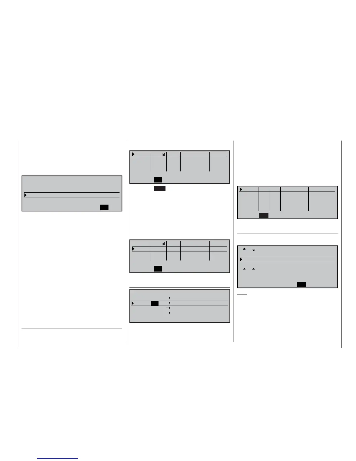
»Model type« (Seite 70)
SEL
Offset +100%
2 AIL 2 FL
MODELTYPE
Tail type
Aileron/camber flaps
Brake
Input 1
Normal
Motor on C1 None
… leave “Motor on C1” to “none” and the tail type at
“normal”. However, you must set “2 AIL 2 FL” in the
“Ailerons / camber fl aps” line for this model confi gura-
tion. In the “Brake” line set or leave “Input 1”, because
the associated C1 stick is to be used as the transmit-
ter control for operating the two airbrake servos con-
nected to receiver sockets 1 + 8.
The Offset value defi nes the neutral position of all the
mixers in the “Brake settings” sub-menu of the »Wing
mixers« menu. Place this neutral point at about
+90%; this assumes that the airbrakes are to be re-
tracted at the forward position of the C1 stick. The re-
minder of the travel between 90% and the full travel of
the stick (100%) is then an intentional dead zone with
these two mixers; this ensures that the control sur-
faces affected by the mixers set up in the “Brake set-
tings” menu remain in their “normal” position even if
the C1 stick is moved slightly away from its end-point.
At the same time the effective travel of the transmitter
control is automatically expanded back to 100%.
In the menu …
»Control adjust« (page 78)
… assign a switch to the fl ight phase independent in-
put 9 for operating the aero-tow release. The travel of
the control for triggering the switch can be adjusted
using the “-travel+” column.
0%
+
100%+100% 0.0 0.0
0% +100%+100% 0.0 0.0
0% +100%+100% 0.0 0.0
0% +100%+100% 0.0 0.0
SYM ASY
ASYSYM
SEL
SEL
«normal »
7
12
11
10
9
offset –time+
Input
Input
Input
Input
free
free
free
–travel+
Pressing the HELP button with the rotary control
pressed in now takes you to the »Servo display«,
where you can check the effect of these settings.
Since the C1 control is required to operate servo 8
as well as servo 1, this link must be created using the
»Control adjust« and »Receiver output swap« me-
nus.
Move at fi rst to the line for the fl ight phase indepen-
dent “input 10” and assign “transmitter control 1” to it
as follows:
0%
+
100%+100% 0.0 0.0
Cnt. 1 0% +100%+100% 0.0 0.0
0% +100%+100% 0.0 0.0
0% +100%+100% 0.0 0.0
SYM ASY
ASYSYM
SEL
SEL
«normal »
7
12
11
10
9
offset –time+
Input
Input
Input
Input
free
free
–travel+
With this stage complete, move to the menu …
»Receiver output swap« (page 153)
SEL
7
7
9
8
8
9
10
10
Servo
Servo
Servo
Servo
RECEIVER OUTPUT
Output
Output
Output
Output
… and swap over servos 8 and 10, so that the signal
for servo 10 is present at (receiver) output 8, and that
for servo 8 at output 10. For more details on this pro-
cedure please turn to the section entitled “Servos run-
ning in parallel” on page 172.
The travels, and – if necessary – the direction of ro-
tation of the airbrake servo 1 and the second airbra-
ke servo, which still constitutes servo 10 as far as the
transmitter’s internal processing is concerned, can be
adjusted in the menu …
»Servo adjustment« (page 74)
Servo 1 => 0% 100% 100% 150% 150%
Servo 2 => 0% 100% 100% 150% 150%
Servo 3 => 0% 100% 100% 150% 150%
Servo 4 => 0% 100% 100% 150% 150%
Rev
SEL SYM ASY SYM
ASY
cent. – travel + – limit +
SEL
In the multi-fl ap menu of the menu …
»Wing mixers« (page 110)
… you should now enter the fi rst mixer values for the
four wing fl aps (two ailerons and two fl aps):
+100% + 60%
Diff. + 50% + 30%
0% 0%
0% 0% +100% +100%
0% 0% 0% 0%
AILE
SEL
SEL
+100%
FLAP
+ 60%
AI
Ail–tr
Fl.pos
FL
El–
>
Fl
Note:
The parameter values shown in this example will vary
from model to model, and will need to be optimised in
the course of a fl ight testing programme.
In the line …
Ai
: … you defi ne the extent in percentage
terms to which the two pairs of control sur-
faces “AILE” and “FLAP” are to follow the ai-
leron control system. When setting the para-