33
Switch assignment / Function fi elds
Using the transmitter control switches “G1 … G8”
For some special functions it may be preferable to
trigger the switching action at a particular position of
a transmitter control, rather than manually using a
normal switch (SW). Of course, you can vary the posi-
tion of the control when the switch is triggered.
Eight switches of this type, termed control switches
G1 ... G8, are available for this purpose; their swit-
ching direction can be reversed (inverted) in the
»Control switches« menu; see page 94.
How to assign a control switch
Starting from the selected (and therefore highlighted)
switch symbol (
) in the appropriate menu, just
operate the desired transmitter control when the win-
dow …
… is superimposed on the screen.
The direction of movement when you assign the con-
trol also determines the switching direction “Switch
open / closed”. A switch symbol after the assignment
indicates the switch status: “ ” or “ ”.
However, if the switching direction is not correct, the
solution is to press the CLEAR button to erase the
control switch when the window shown above is su-
perimposed, and then re-assign the control switch
with the new switching direction, as described above.
Note:
All the switches described thus far can also be
assigned to multiple functions. Please take care
to avoid ACCIDENTALLY assigning several func-
tions to one switch where they could interfe-
re with each other. We recommend that you write
down the switch functions you have assigned.
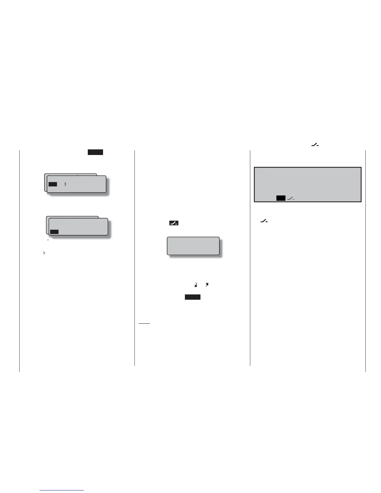
Move desired switch
to ON position
(ext. switch: ENTER)
the window, i. e. by pressing the ENTER button: a
new window now appears showing a list containing
the two fi xed switches “FX” and the logical switches
“L1 … L8” and “L8i … L8i”:
Turn the rotary control to select the desired switch; if
you reach the end of the second line you will see the
switches L3i to L8i superimposed:
Fixed switches
The two FX switches turn a function either on (“FXI”)
or off (“FX
”) permanently.
Logical switches
Using the logical switches – see »Logical switches«
menu, page 97 – you can link together two switches
and / or control switches logically in an “AND” or “OR”
manner. The software provides a total of eight logical
switches “L1 … L8” (plus a further eight inverted logi-
cal switches, with the opposite switching direction).
However, the outcome of one of these logical swit-
ched functions can equally well be used as a swit-
ched function in a further logical switch arrangement.
See the appropriate menu for more details of this.
Gewünschten Schalter
oder Geber betätigen
(erw. Schalt.: ENTER)
Logical / fixed switch
FX L1 L2
FXI
L3 L4
L5 L6 L7 L8 L1i L2i
In certain menus you will see function fi elds in the
bottom line of the screen; they can be called up using
the rotary control:
TOG ASY
SYM
SEL
STO CLR ENT
• TOG: Include / suppress menus
• SEL (select): Select
• : Switch symbol fi eld (assigning swit-
ches, control switches and logical
switches)
• STO (store): Store (save) (e. g. transmitter control
position)
• CLR (clear): Erase (e. g. curve reference point)
• SYM: Adjust values symmetrically
• ASY: Adjust values asymmetrically
• ENT (enter): Only in the »Code lock« menu
•
: Switch to second page (next menu)
within a menu
Function fi elds
SEL, STO, CLR, SYM, ASY, , TOG,
, ENT
Gewünschten Schalter
oder Geber betätigen
(erw. Schalt.: ENTER)
FXI
L5 L6 L7 L8 L1i L2i
L3i L4i L5i L6i L7i L8i
Logical / fixed switch