89
Program description:
Transmitter controls
The Dual Rate curve is shown simultaneously in the
graph (pressing CLEAR = 100%).
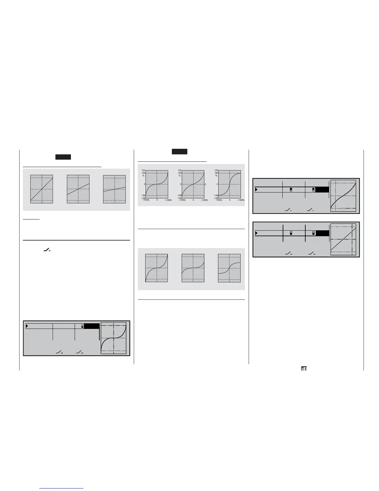
Examples of different Dual Rate values:
Caution:
In the interests of safety the Dual Rate value should
always be at least 20% of total control travel.
Exponential function
If you wish to switch between two possible settings,
select the
fi eld and assign one of the availab-
le switches to the function, as described on page 32.
The assigned switch appears in the screen display to-
gether with a switch symbol which indicates the direc-
tion of operation when you move the switch.
For example, the system enables you to fl y with a li-
near curve characteristic in the one switch positi-
on, and to pre-set a value other than 0% in the other
switch position.
To change the Expo value, fi rst select the right-hand
SEL fi eld, then use the rotary control in the highligh-
ted fi eld to set separate values for each of the two
switch positions, e. g. in the “normal” fl ight phase:
100% 2
+100%
«Normal »
SEL
SEL
100%
0%
100% 0%
DUAL EXPO
Roll
Pitch ax.
Tail rot.
The Expo curve is displayed simultaneously in the
graph. (Pressing CLEAR = 0%.)
Examples of different Expo values:
In these examples the Dual Rate value is 100% in
each case.
Combination of Dual Rate and Expo
If you have assigned Dual Rates and Expo to the
same switch, both functions are switched simultane-
ously, e. g.:
Asymmetrical setting of Dual Rate and Expo
If you wish to set asymmetrical Dual Rate and / or
Expo values, i. e. varying according to the direction
of stick movement, you must move to the »Control
switches« menu and assign, say CONTROL 3 (pitch-
axis / elevator stick) to one of the control switches
G1 ... G8. After this move to the »Dual Rate / Expo«
menu and select the corresponding control function,
in this case “pitch-axis”. Now activate “Switch assign-
ment”, and move the transmitter control you just se-
lected.
Move to the SEL fi eld of the “DUAL” or “EXPO” co-
lumn, move the “pitch-axis” stick to the appropriate
end-point, and enter the Dual Rate and / or Expo va-
lue for each side of neutral using the rotary control in
the highlighted fi eld, e. g. for …
“pitch-up”:
100%
100% +30%
«Normal » DUAL EXPO
SELSEL
100% 0%
0%
G3G3
Roll
Pitch ax.
Tail rot.
and “pitch-down”:
0%
90% G3
+
0%
«Normal » DUAL EXPO
SELSEL
100%
G3
100% 0%
Roll
Pitch ax.
Tail rot.
The dotted vertical line shows the current position of
the pitch-axis stick.
0
1 0 0
1 2 5
%
+ 1 0 0 %
- 1 0 0 % 0
- 1 0 0
- 1 2 5
0
1 0 0
1 2 5
%
+ 1 0 0 %
- 1 0 0 %
0
- 1 0 0
- 1 2 5
+ 1 0 0 %
- 1 0 0 % 0
0
1 0 0
1 2 5
%
- 1 0 0
- 1 2 5
Dual Rate = 100%
Dual Rate = 50% Dual Rate = 20%
Servo travel
Servo travel
Servo travel
Stick defl ection Stick defl ection Stick defl ection
Expo = +100%
Expo = +50% Expo = -100%
Servo travel
Servo travel
Servo travel
Stick defl ection
Stick defl ection Stick defl ection
+ 1 0 0 %
- 1 0 0 %
0
+ 1 0 0 %
- 1 0 0 % 0
+ 1 0 0 %
- 1 0 0 % 0
0
1 0 0
1 2 5
%
- 1 0 0
- 1 2 5
0
1 0 0
1 2 5
%
- 1 0 0
- 1 2 5
0
1 0 0
1 2 5
%
- 1 0 0
- 1 2 5
Expo = +100%, D/R = 125%
Expo = +50%, D/R = 50% Expo = -100%, D/R = 50%
Servo travel
Servo travel
Servo travel
Stick defl ection Stick defl ection Stick defl ection