910FS Splicer
Greenlee / A Textron Company 4455 Boeing Dr. • Rockford, IL 61109-2988 USA • 815-397-7070
48
Testing Splicing Splice-on Connectors (SOC)
The 910FS can fusion splice SOC using the universal SOC adapters. Be sure to select
the correct SOC to match the eld bers before splicing.
The following procedure should be used to practice fusion splicing with SOC:
1. Identify the eld ber type by consulting the ber manufacturer’s data sheet.
2. Obtain a “ber patch cord” with same ber and connector style as the SOC that will
be used.
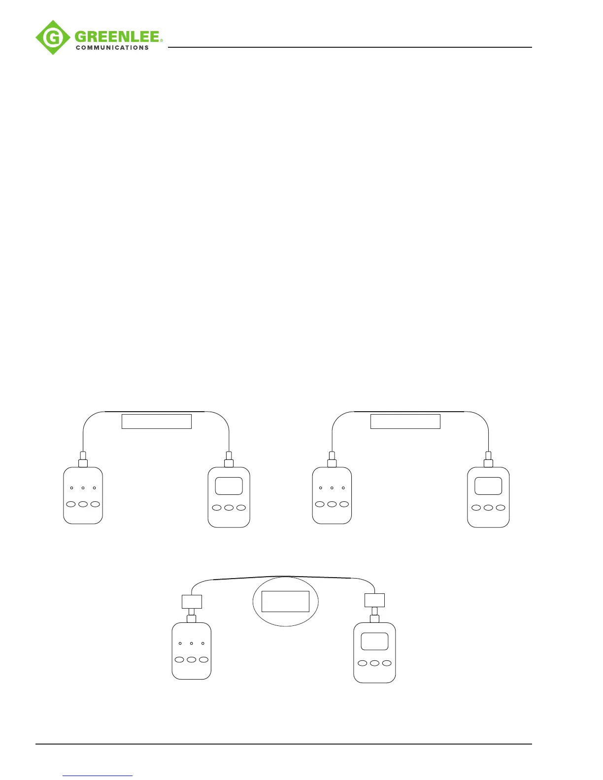
3. Connect a laser (SM) or LED (MM) source to one end of the ber and a power meter
to the other end of the ber. Refer to Figure 3.
4. Zero the power meter. Refer to Figure 4.
5. Obtain an approximately 10 m length of ber (same as the eld ber).
6. Determine if this ber type has a pre-programmed splicing prole in the 910FS.
Usethis prole for splicing.
7. If there is not an exact matching splice prole, use the AUTO mode splicing prole.
8. Splice a SOC to each end of the ber. This will be called the “SOC spliced patch
cord.”
9. Replace the “ber patch cord” with the “SOC spliced patch cord.” The power meter
should read 0dB PLUS allowable splice loss X2. Refer to Figure 5.
10. The splicing technician should repeat steps 8 and 9 until they are able to reliably
splice using the SOC.
Fiber Patch Cord
On/Off
1
st
λ 2
nd
λ
Optical Source
On/Off
λ dB/dBm
Power
Meter
Fiber Patch Cord
On/Off
1
st
λ 2
nd
λ
Optical Source
On/Off
λ dB/dBm
0 dB
Figure 3 Figure 4
On/Off
1
st
λ 2
nd
λ
Optical Source
On/Off
λ dB/dBm
SOC
SOC
SOC Spliced
Patch Cord
0 dB
Figure 5