910FS Splicer
Greenlee / A Textron Company 4455 Boeing Dr. • Rockford, IL 61109-2988 USA • 815-397-7070
15
Splicing Procedure
To ensure a good splice, the optical ber is observed with the image processing system
equipped in the 910FS. However, in some cases the image processing system cannot
detect a faulty splice. Visual inspection with the monitor is often necessary for better
splicing yield. Observe the following standard operating procedure:
• After bers are loaded into the splicer, press and the bers will move toward each
other. The ber motion stops and the cleaning arc is performed. The cleave angle
and end-face quality are checked. If the measured cleave angle is greater than its
set threshold or ber chipping is detected, the beeper sounds and an error message
warns the operator. The splicing procedure pauses. If no error message is displayed,
the below stated end-face conditions are used for visual inspection. If observed,
remove the ber from the splicer and repeat ber preparation. These ber cleave
defects may cause a faulty splice.
Chip Lip Incline
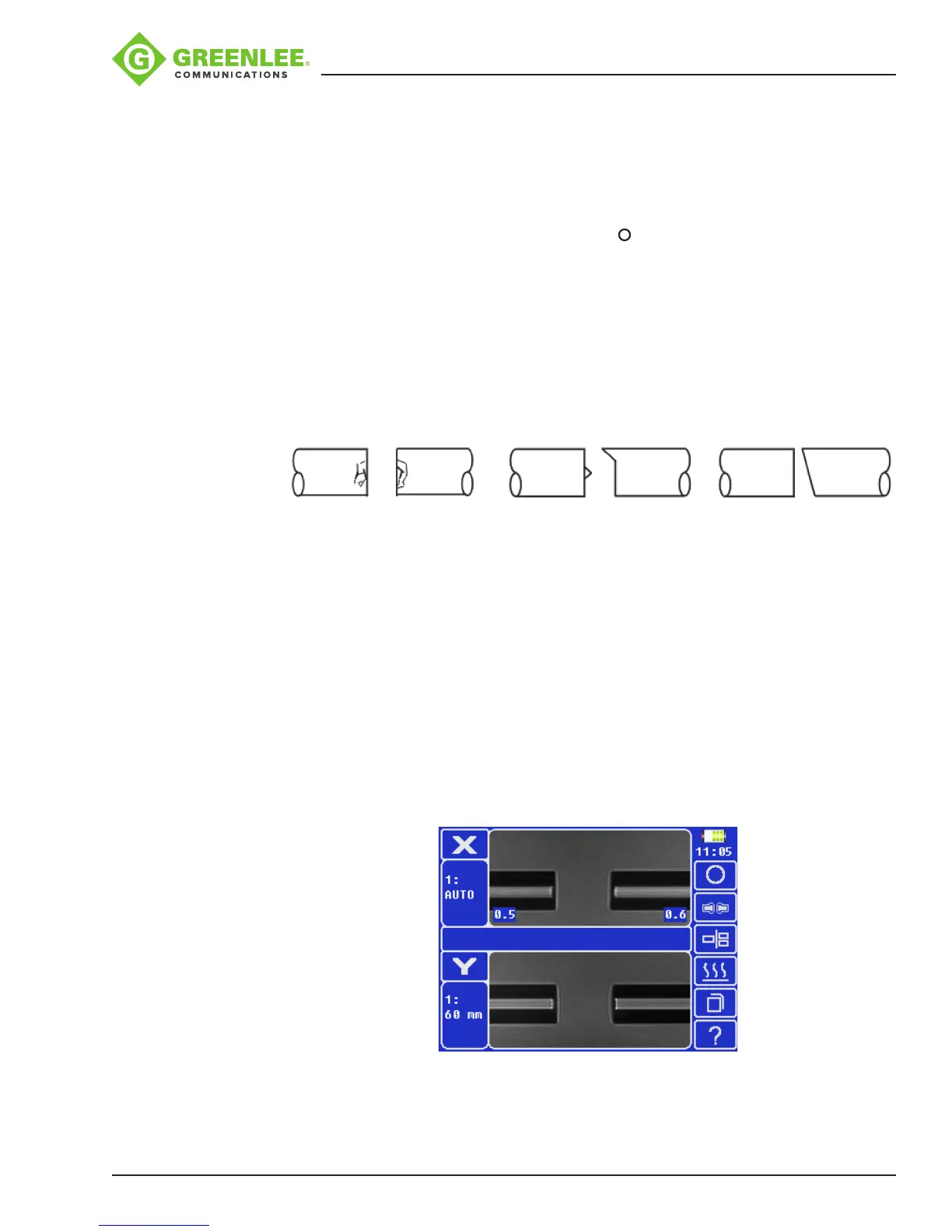
• After ber inspection, the bers are aligned core-to-core or cladding-to-cladding.
Cladding axis offset and core axis offset measurements can be displayed.
• After completion of ber alignment, an arc discharge is performed to splice the
bers.
• Estimated splice loss is displayed upon completion of splicing. Splice loss is
affected by factors stated in Section 5. These factors are taken into account
to calculate, or estimate, splice loss. The calculation is based on dimensional
parameters, such as MFD, cleave quality, and fusion splice shape after the splice.
If either the cleave angle measured or the estimated splice loss exceeds its
set threshold, an error message is displayed. If the spliced ber is detected as
abnormal, such as “Fat”, “Thin” or “Bubble”, an error message is displayed. If no
error message is displayed but the splice looks poor by visual inspection through the
monitor, it is strongly recommended to resplice.