910FS Splicer
Greenlee / A Textron Company 4455 Boeing Dr. • Rockford, IL 61109-2988 USA • 815-397-7070
17
Heating Protection Sleeve
1. Transfer the ber with protection sleeve from the centering device to the tube heater.
2. Close the tube heater lid.
Notes:
• Make sure the splice point is located at the center of the protection sleeve.
• Make sure the strength member in the protection sleeve is placed downward.
• Make sure the ber is not distorted.
• The splice-on connector must be installed on the right-hand side of the splicer
heater. Use heater prole #1 for the SOC.
3. Press to start tube heating. The beeper sounds and the HEAT LED (red color)
turns off when tube heating is completed.
4. Open the tube heater lids and remove the protected ber from the tube heater. Apply
some tension to the ber while removing it from the tube heater.
5. Visually inspect the nished sleeve to verify that no bubbles or debris/dust is present
in the sleeve.
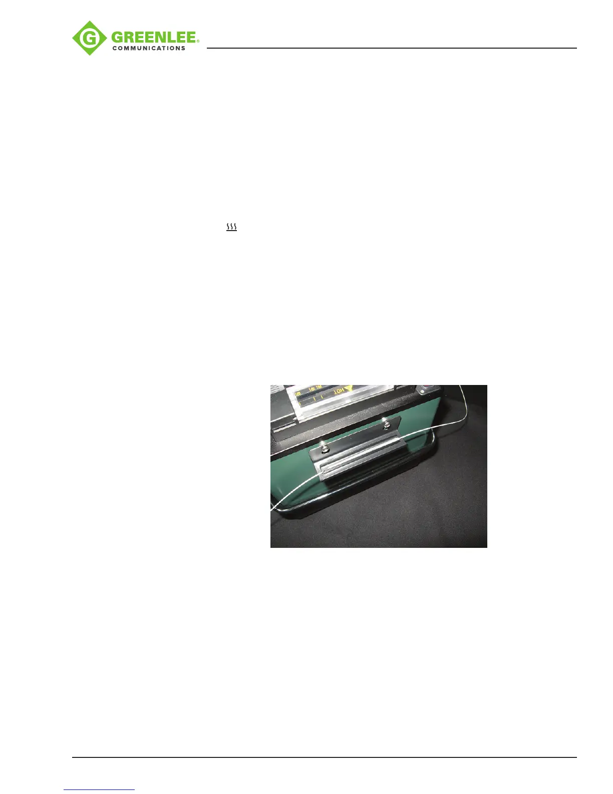
Cooling Tray
Place the splice into the cooling tray on the back of the 910FS splicer.
Splice-on Connectors
The 910FS uses the Greenlee version of splice-on connectors. The 910FS currently
supports SC, LC, FC, and ST versions (both PC and APC nish, where applicable).
Follow the instructions supplied with the SOC packaging.