910FS Splicer
Greenlee / A Textron Company 4455 Boeing Dr. • Rockford, IL 61109-2988 USA • 815-397-7070
49
Appendix C. Greenlee Splice-on Connectors
Note: This splice-on connector is compatible with 900 µm optical ber.
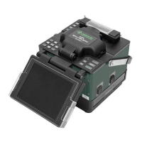
Greenlee splice-on connector contains the following items:
A. (1) Handle, each kit contains a limited number
B. (1) Outer housing (SC style only)
C. (1) Splice-on connector (SOC) pigtail with cleave protector and ber alignment
sleeve
D. (1) 27 mm mini splice sleeve
E. (1) Universal strain relief boot
F. (1) Fiber positioning tool (not pictured)
Note: If ber alignment sleeve has become separated from the SOC body, do not
attempt to re-install; discard it.
A B C D E
Cable Preparation
Slide the 900 μm strain relief boot and then the 27 mm mini splice protective sleeve over
the 900μm eld ber. Use the 910CL to cleave the eld ber. Insert the ber adapter
with the cleaved ber into the left-hand side of the 910FS fusion splicer. Make sure to
butt the 900 μm buffer up to the edge of the ber adapter. This will ensure that the mini
splice sleeve will adhere to both sides of the 900 μm buffer.
Installation
1. Disable the “Proof Test” on the fusion splicer.
2. Remove the factory dust cap from the connector.
Note: The extended dust cap may be placed on at this time, if so desired, to aid in
the transfer of the connector. DO NOT LEAVE THE EXTENDED DUST CAP ON THE
CONNECTOR, INSIDE THE FUSION SPLICE MACHINE.
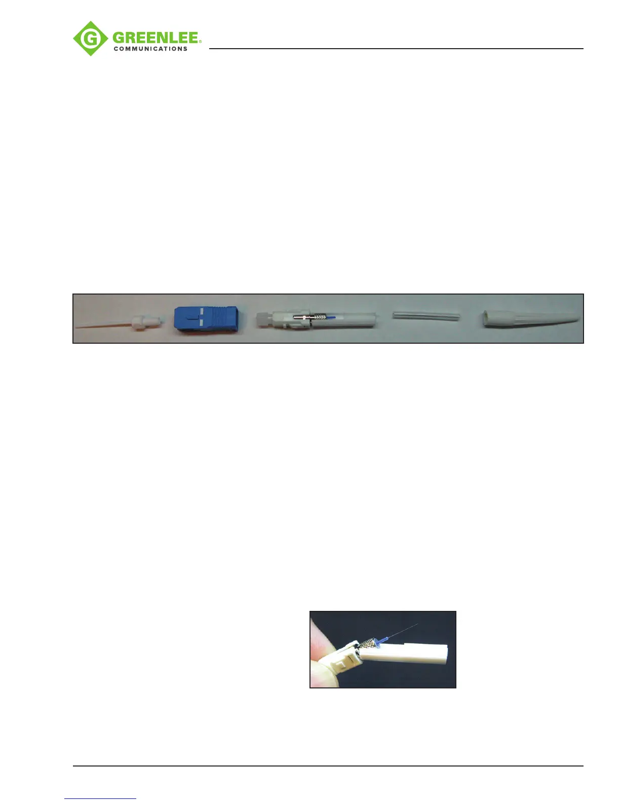
3. While holding the connector rmly, pull down on the cleave protector to remove it
from the connector (Figure 1).
Note: Do not touch the cleaved ber stub with the protector or your ngers as this
may damage the factory cleave.
Figure 1