910FS Splicer
Greenlee / A Textron Company 4455 Boeing Dr. • Rockford, IL 61109-2988 USA • 815-397-7070
50
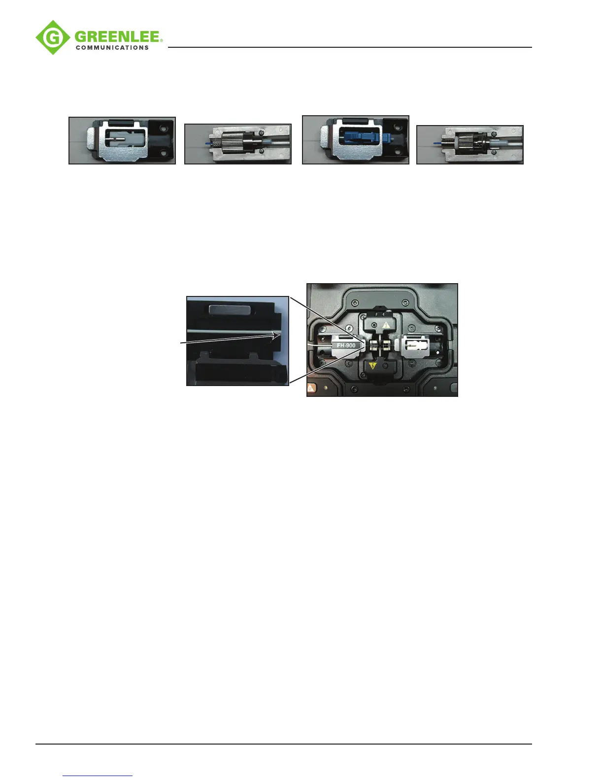
4. Insert the connector into the universal splice-on connector holder so that the back
end of the connector is ush with the end of the holder (Figures 2-5). Once aligned
properly, the connector should t freely into the holder with no force required.
Figure 2 (SC) Figure 3 (FC) Figure 4 (LC) Figure 5 (ST)
5. Insert the holder into the right-hand side of the splicer (Figure 6), making sure that
the ber stub lays properly into the V-groove block of the splicer. You may use the
ber positioning tool to help align the ber in the V-groove. The ber for FC and ST
splice-on connectors must have the ber laying in the end of the ber groove in the
V-groove. The ber positioning tool can be used to align the ber with the V-groove.
Turning the ber and/or the connector may also be necessary to accomplish this.
The FC/ST ber adapter may also need to be twisted slightly to ensure that the ber
is aligned with the V-groove.
Note: Make sure that
the edge of the 900
micron tight buffer is
even with the edge of
the 900 micron fiber
adapter.
Note: Remove the
extended dust cap
before initiating the
fusion splice.
Figure 6
6. Perform the fusion splice as described in the fusion splicer manufacturer’s
instructions.
7. Once the fusion splicing cycle is completed, remove the connector from the splicer
and slide the splice protection sleeve up to cover the splice. Make sure that the
splice protector is positoned against the connector body.
Note: The extended cap may be put in place now to aid in the transfer to the splice
sleeve oven.
8. Transfer the splice to the splice sleeve heat oven on the right-hand side (Figure
7). Verify the position of the splice sleeve is butted up against the metal portion of
the splice-on connector. Use the 60 mm heater mode #1 with center and edges
activated. Press the HEAT button to run the shrink cycle.
9. Verify that the splice protection sleeve is completely shrunk onto the ber to avoid
the end catching on the strain relief boot. If the splice sleeve is not completely
shrunk, then place it back in the sleeve oven and initiate a second heat cycle.
Note: Make sure that the splice sleeve has fully cooled before sliding the strain relief
boot into place. For SC connectors, install the outer housing onto the connector,
being sure to align the angled corners of the inner housing with those of the outer
housing (Figure 8).