CM220 Chipper 6. MAINTENANCE 6-4
©GreenMechLtd 6-4 08/17
6.6 Drive belts - Daily
Check tension by engaging clutch with engine stopped. If
belts are slack, undo tensioning nut (fig 6.6.1) sufficiently to
transfer engine weight onto belts. If nut is less than three
threads from end, replace belts (section 6.9).
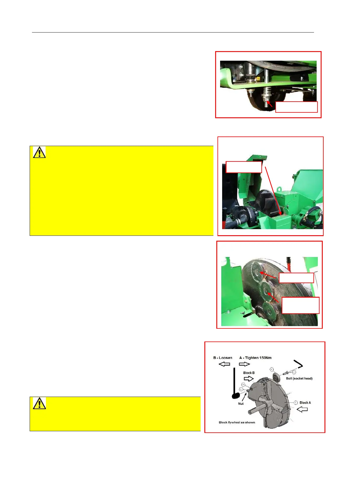
6.7 Disc Blade Rotation And Replacement
The design of the disc blades permits relocation in at least
three rotated positions before regrinding or replacement is
required.
1 Check engine is switched off and start key removed.
2 Raise engine cover and check any rotation has stopped.
3 Remove single bolt retaining chipper flywheel cover (fig
6.7.1).
CAUTIONS for Blade cleaning
x Blades have sharp edges. Wear protective gloves.
x Flywheel paddles and vanes create shearing and trapping points
at edges of exposed housing. Do not place hands or fingers on
or near flywheel and housing edges.
x Flywheel rotation may be resisted by engine compression in
either direction. Beware unexpected movement when manually
rotating flywheel between blade positions.
x Tools can slip if not fully engaged. Clean fasteners thoroughly
before applying tools.
x Ensure flywheel is prevented from rotating when applying force to
tools on blade fasteners.
Follow procedure below:
1 Wear protective gloves.
2 Remove flywheel cover bolt.
3 Using discharge chute handle as a lever, swing back cover on to
stop to expose flywheel and disc blades. (fig 6.7.1, Fig 6.7.2).
4 Block flywheel securely with bar to prevent anticlockwise turn
(viewed from blade nut).
5 Thoroughly clean debris from nut faces and bolt head socket.
6 Using socket tool, loosen nut anticlockwise. Support blade bolt
with hexagon key as required and remove disc blade and fasteners
(fig 6.7.3).
7 Thoroughly clean debris from flywheel blade housing and all
components to be replaced. Inspect condition of nuts and bolts and
replace if any signs of wear.
8 Replace blade ensuring that flywheel is blocked for opposite
rotation. Tighten to correct torque: 150Nm.
Remove flywheel block and carefully rotate to next blade and
repeat next blade removal (from 4 above) until all disc blades
cleaned and replaced securely.
9 Replace all covers.
10 Check all covers are secure.
11 Replace key to start machine.
CAUTION! Disc blades must only be sharpened by
grinding angled back face on a bench grinder. Grinding of front
face will upset gap, which is factory set. Do not sharpen with
hand held equipment.
All disc blades must be sharpened in “sets” with equal amounts
removed to maintain balance. See 6.24
Note. If any disc blades are worn below flat annular section a complete set should be replaced.
Fig 6.7.1 Chipper flywheel cover
Bolt
Fig 6.7.3. Flywheel and blades
Fig 6.6.1 Drive belt tension
d
ustment
Fig 6.7.2 Chipper flywheel and disc
blades
Torque to