Cycle Analyst V3.1 User Manual
Rev 1.0
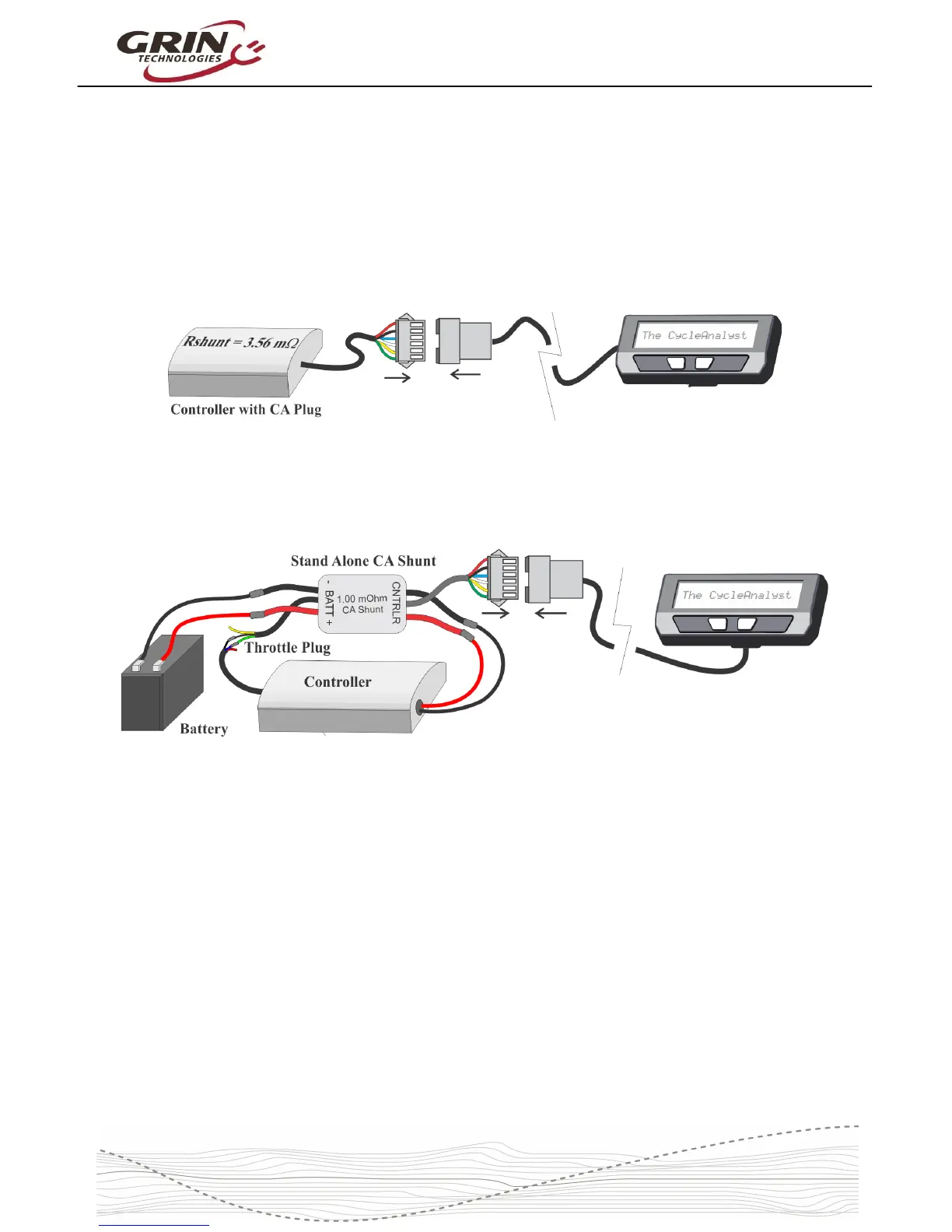
3.2 Shunt / Controller Wiring
For systems that have a CA3 compatible motor controller, the electrical hookup is
simply a matter of connecting the 6-pin CA plug to the mating plug on the
controller. This JST-SM connector standard has pins for the battery voltage,
throttle signal, speedometer signal, and current sense resistor leads.
If your controller doesn't have a compatible CA plug on it, then you will need to
use the Stand Alone Shunt wired inline with the + and – battery leads in order for
the CA to see the battery current and voltage.
The Stand Alone CA3 Shunt has a short unterminated cable with 3 signal wires
in it. The green signal wire is the throttle output of the Cycle Analyst, and that
should be wired to the throttle input plug of your motor controller. Without this
connection, the CA3 can monitor and display speed and battery consumption but
has no way to regulate and control the motor power.
The CA3 turns on whenever there is voltage on the CA plug. With direct plug
connections, if the controller has an on/off switch this would also turn the CA on
and off. If the controller does not have an on/off switch or the Stand Alone CA
shunt is used, then the the battery itself should have an on/off switch for turning
the CA on and off.
Please refer to section 6.13 about setting the Cycle Analyst Rshunt value,
especially if you are connecting the CA3 directly to a motor controller.
6