-4-
Model G0761 (Mfd. Since 10/13)
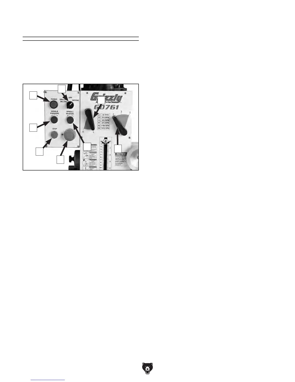
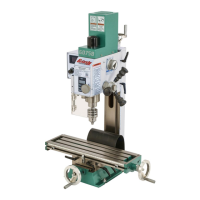
Basic Controls
Use Figure 1 and the descriptions below to gain
a basic understanding of the control panel and
spindle speed controls. Knowing this information
is required to safely complete the Test Run in the
SETUP section.
A. POWER Lamp: Illuminates when the machine
is connected to power.
B. Mode Switch: Sets the spindle mode to
either drilling/milling or tapping.
C. High/Low Range Lever: Selects either high
or low spindle speed range.
D. Spindle Speed Lever: Selects one of three
spindle speeds in the selected speed range.
E. SPINDLE REVERSE Button: Starts coun-
terclockwise spindle rotation (as viewed from
above). The spindle must be completely
stopped before this button is pushed.
F. EMERGENCY STOP Button: Cuts power
to the spindle motor and remains depressed
until reset. Twist clockwise until it pops out to
reset.
G. STOP Button: Stops spindle rotation.
H. SPINDLE FORWARD Button: Starts clock-
wise spindle rotation (as viewed from above).
The spindle must be completely stopped
before this button is pushed.
Figure 1. Control panel and spindle speed
controls.
A
B
C
F
G
H
E
D