11.
Figure 12
8.
Figure
12
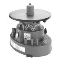
Figure 12. Table stop bolt (table tilted for clarity).
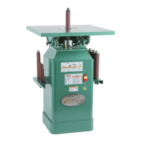
Figure 13. Pointer adjustment.
12.
Figure 14
13.
Figure 15
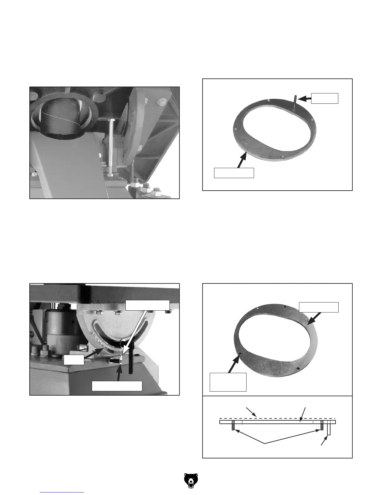
Note: The roll pins and set screws must not
protrude above the top surface of the table
insert or they will interfere with sanding oper-
ations.
Figure 14. Inserting roll pins (bottom view).
Figure 15. Inserting set screws.
Flat Top Surface
Set Screws
Roll Pin
Table Insert
9.
10. Figure 13
 Loading...