-4-
Model G7945/G7946 (Mfd. Since 09/17)
Controls &
Components
To reduce your risk of
serious injury, read this
entire manual BEFORE
using machine.
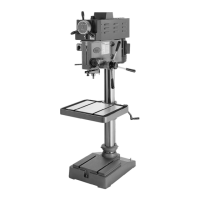
Refer to the following figures and descriptions to
become familiar with the basic controls and com-
ponents of this machine. Understanding these
items and how they work will help you understand
the rest of the manual and minimize your risk of
injury when operating this machine.
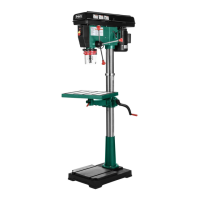
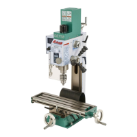
A. Power Switch: Turns motor ON/OFF.
B. Headstock: The cast-iron upper portion of
the drill press, which houses the quill and
supports the motor and belt housing.
C. Belt Cover: Provides access to drive belt for
spindle-speed changes.
D. Belt Tension Lock Knobs: Secures motor in
position to set belt tension.
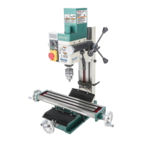
I. Headstock 90° Lock Pin: Engages when
headstock is positioned with spindle at 90° to
table. When pulled out, allows headstock to
be tilted left/right.
J. Scale: Indicates headstock angle.
K. Spindle Return Spring: Automatically
returns quill into headstock.
L. Depth Stop: Limits quill travel to a pre-set
drilling depth.
M. Spindle: Used to mount chuck and milling
accessories with a JT#33 taper.
N. Table Rotation Lock Lever: Locks table
rotation.
O. Column Lock Lever: Locks table height.
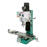
Figure 2. Machine controls (right).
E. Horizontal Adjustment Knob: Moves the
headstock forward and backward over the
column.
F. Downfeed Handles: Move the quill up and
down.
G. Table Height Crank Handle: Raises/lowers
table.
H. Chuck Guard & Chuck: Chuck guard pro-
tects user from flying debris; chuck accepts
drill bits from
1
⁄16" to
5
⁄8" and mounts to the
spindle with a JT#33 taper.
G
B
C
E
Figure 3. Machine controls (left).
H
J
D
N
I
L
M
K
A
F
D
O