-22-
Model G7947/G7948 (Mfd. Since 01/21)
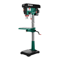
6. Place rack inside of table support assembly,
mesh it with pinion, and slide table support/
rack assembly over column, as shown in
Figure 17.
Figure 17. Sliding table support and rack over
the column.
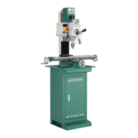
7. Slide column ring over column with beveled
edge facing down, as shown in Figure 18,
then fit beveled edge of column ring over rack
and tighten set screw.
Note: Do not overtighten the set screw or you
may split the column ring. Also make sure the
rack is seated firmly in the lower ring.
10.
Thread large lock lever into back of table sup-
port assembly approximately three turns, for
now.
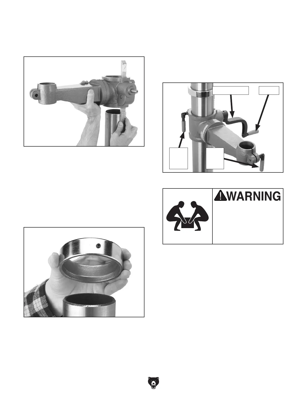
11.
Thread small lock lever into front part of table
support assembly approximately three turns,
for now. The assembly should match what is
shown in Figure 19.
12.
Set top piece of headstock Styrofoam pack-
ing approximately 6 feet away from column/
base assembly.
13.
Remove headstock from box and place it on
Styrofoam packing you laid out in Step 1.
Note: To avoid damaging the machine, be
careful not to hold the headstock by the
switch or the top part of the belt cover when
lifting.
14.
Carefully lay column/base on its side.
15. Slide column all the way into bottom of head-
stock (approximately 4"-6").
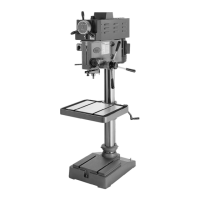
The headstock is very
heavy. You MUST have
assistance when moving,
lifting or mounting the
headstock on the column
and base assembly.
Figure 18. Correct column ring orientation.
8. Install crank lever over pinion shaft, and
tighten set screw in crank handle against flat
part of pinion shaft.
9.
Thread handle into crank lever.
Figure 19. Handles and lock levers installed.
Crank Handle Handle
Small
Lock
Lever
Large
Lock
Lever