-4-
Model G7947/G7948 (Mfd. Since 01/21)
Controls &
Components
To reduce your risk of
serious injury, read this
entire manual BEFORE
using machine.
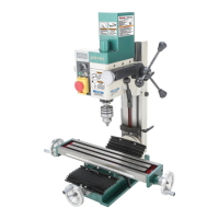
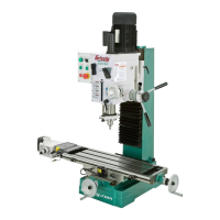
Refer to the following figures and descriptions to
become familiar with the basic controls and com-
ponents of this machine. Understanding these
items and how they work will help you understand
the rest of the manual and minimize your risk of
injury when operating this machine.
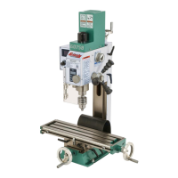
A. Power Switch: Turns motor ON/OFF.
B. Light Switch: Turns light ON/OFF.
C. Headstock: The cast-iron upper portion of
the drill press, which houses the quill and
work light, and supports the motor and belt
housing.
D. Belt Tension Lever: Adjusts motor location
to increase/decrease belt tension.
H. Spring: Automatically returns quill into
headstock.
I. Lash Screw: Removes quill lash.
J. Depth Stop: Limits quill travel to a pre-set
drilling depth.
K. Quill: Houses the spindle and bearings.
L. Spindle: The hollow shaft that accepts the
arbor.
M. Arbor: A tapered shaft that connects the
chuck to the spindle.
N. Chuck: Accepts drill bits with shanks from
3
⁄64" to
5
⁄8" and uses a JT-3 key.
O. Scale: Displays current table-tilt angle.
P. Column Lock Lever: Locks table height.
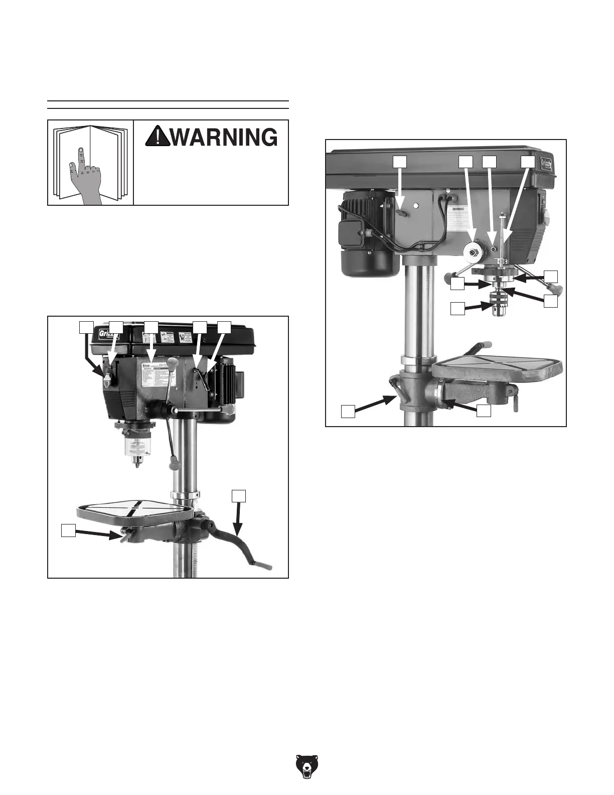
Figure 1. Headstock controls (right).
E. Belt Tension Locks: Two knobs on each
side of headstock lock motor in place.
F. Table Height Crank: Raises/lowers table.
G. Table Lock Lever: Locks table rotation.
G
F
B D EC
Figure 2. Headstock controls (left).
O
IH
P
E J
K
L
M
N
A