Model G7947/G7948 (Mfd. Since 01/21)
-29-
D
C
B
A
4
3
2
1
4
3
2
1
1 RPM 210
BELT:A-1.4-4
D
C
B
A
4
3
2
1
4
3
2
1
2 RPM 310
BELT:B-2.4-4
BELT:
A-1.3-3
D
C
B
A
4
3
2
1
4
3
2
1
4 RPM 440
BELT:C-3.4-4
D
C
B
A
4
3
2
1
4
3
2
1
D
C
B
A
4
3
2
1
4
3
2
1
6 RPM 670
BELT:A-1.2-2
D
C
B
A
4
3
2
1
BELT:
D-4.3-3
D
C
B
A
4
3
2
1
4
3
2
1
8 RPM 1430
BELT:C-3.2-2
D
C
B
A
4
3
2
1
4
3
2
D
C
B
4
3
2
4
3
2
RPM 2050
D
C
B
4
3
2
1
4
3
2
1
RPM 2350
BELT:C-3.1-1
D
C
B
A
4
3
2
1
4
3
2
1
RPM 3300
BELT:D-4.1-1
10
11
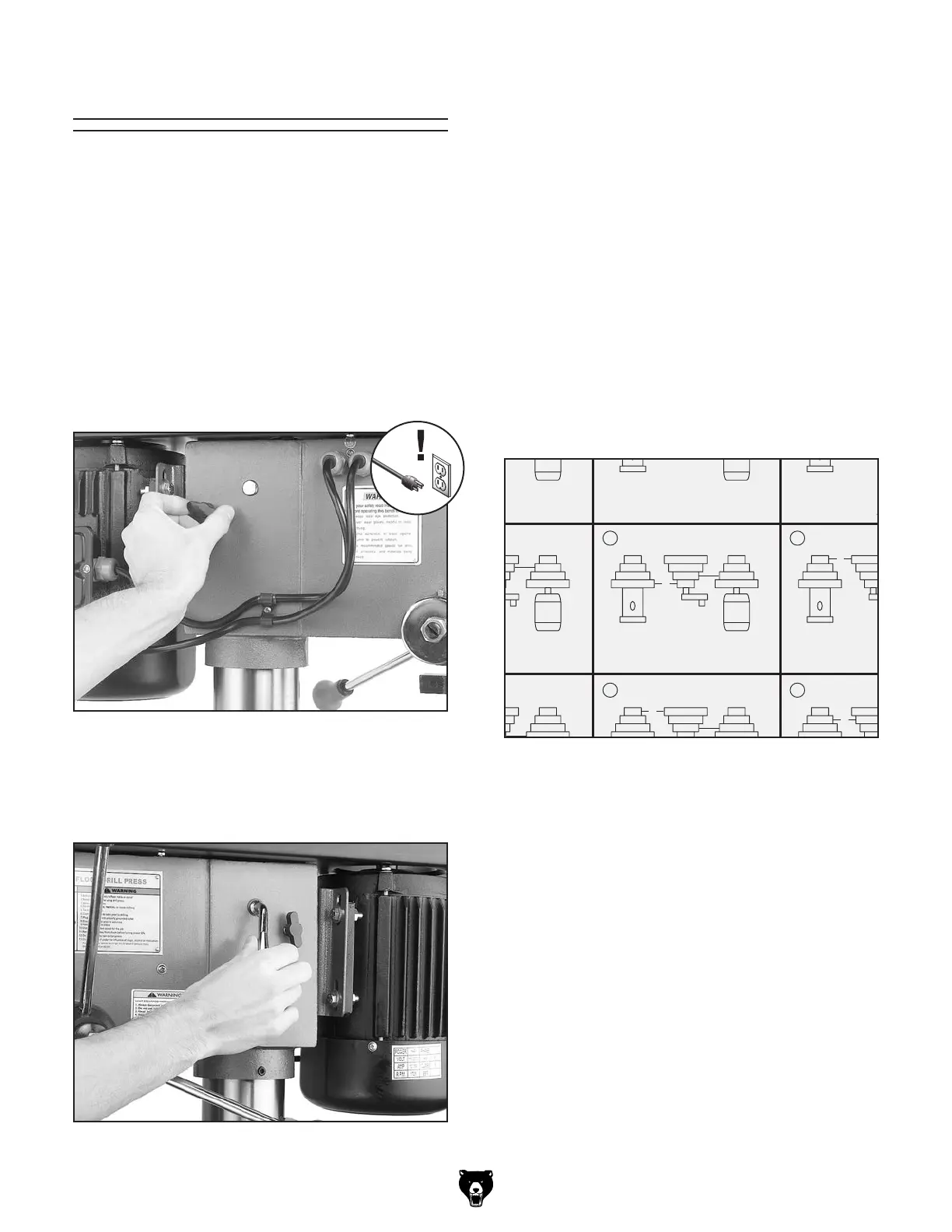
Figure 30. Loosening lock knob (both sides).
Figure 31. Using the belt tension lever.
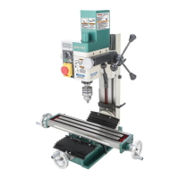
The Model G7947 & G7948 is capable of 12 dif-
ferent spindle speed RPMs. Spindle speed is
controlled by the configuration of V-belts and
pulleys located inside the belt cover on top of the
machine.
To change speeds:
1.
DISCONNECT MACHINE FROM POWER!
2.
Loosen the belt tension lock knobs (shown in
Figure 30) on both sides of the headstock, so
the motor is free to move.
3.
Rotate the belt tension lever clockwise, as
shown in Figure 31, to take tension off the
V-belts.
4.
Locate the desired speed on the speed chart
under the belt cover and move the V-belts
to the desired V-grooves on the motor, idler,
and spindle pulleys.
For Example: As indicated in the speed
chart for 670 RPM (Figure 32), a belt combi-
nation of A-1.2-2 creates 670 RPM.
• The “A-1” refers to the belt position
between the spindle pulley and the idler
pulley.
• The “2-2” refers to the belt position between
the motor pulley and the idler pulley.
Note: Both belts may have to be removed
before certain speed changes can be made.
Figure 32. Pulley combination for 670 RPM for
example.
5. Rotate the belt tension lever until the belts
are tight. Tighten both lock knobs.
6.
Close the cover before plugging in the
machine.
Changing Speeds