16
15
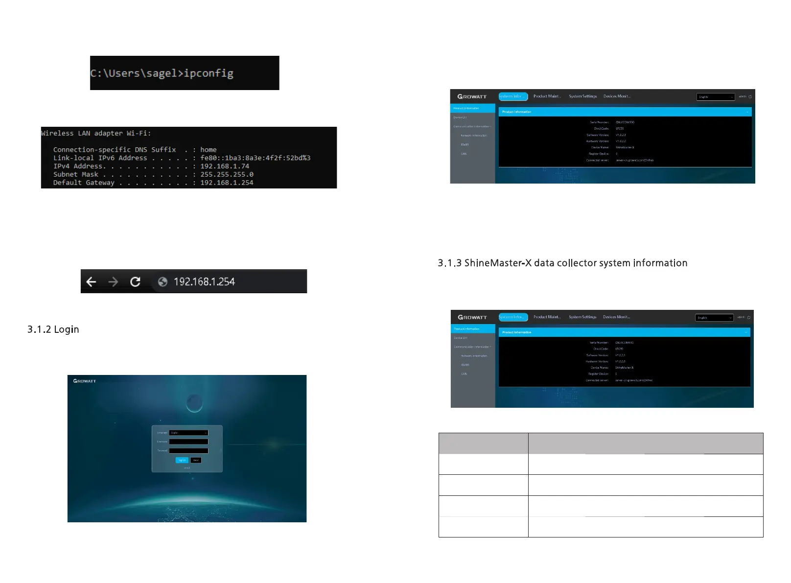
Figure 3-3 Schematic diagram of command line input
Figure 3- 4 Schematic diagram of the results of the ipconfig command
3. Enter 192.168.1.254 in the computer browser to access the built-in page of
ShineMaster-X .
Figure 3-5 Schematic diagram of login IP
1. After successfully accessing the built-in page of ShineMaster-X, the user needs to log in
to modify or set parameters, as shown in the figure below:
Figure 3-6 Login interface
2. Enter the user name and password, the default login user name: admin, password:
admin, click login after filling in, enter the ShineMaster-X system page.
Figure 3- 7 System information bar
3. The system page mainly includes the following four columns
A. System information, B. Product maintenance, C. System settings, D. Equipment
monitoring.
Ÿ Click ShineMaster-X system information to view "product information", "device list",
"communication information" and other information;
Figure 3- 8 System information bar
ShineMaster-X serial number, software version and other
information
Registered device information and online information
Details of wired and wireless networks
Setting information for RS485-1 , RS485-2 , RS485-3 , RS485-4
CAN communication information
 Loading...