8
7
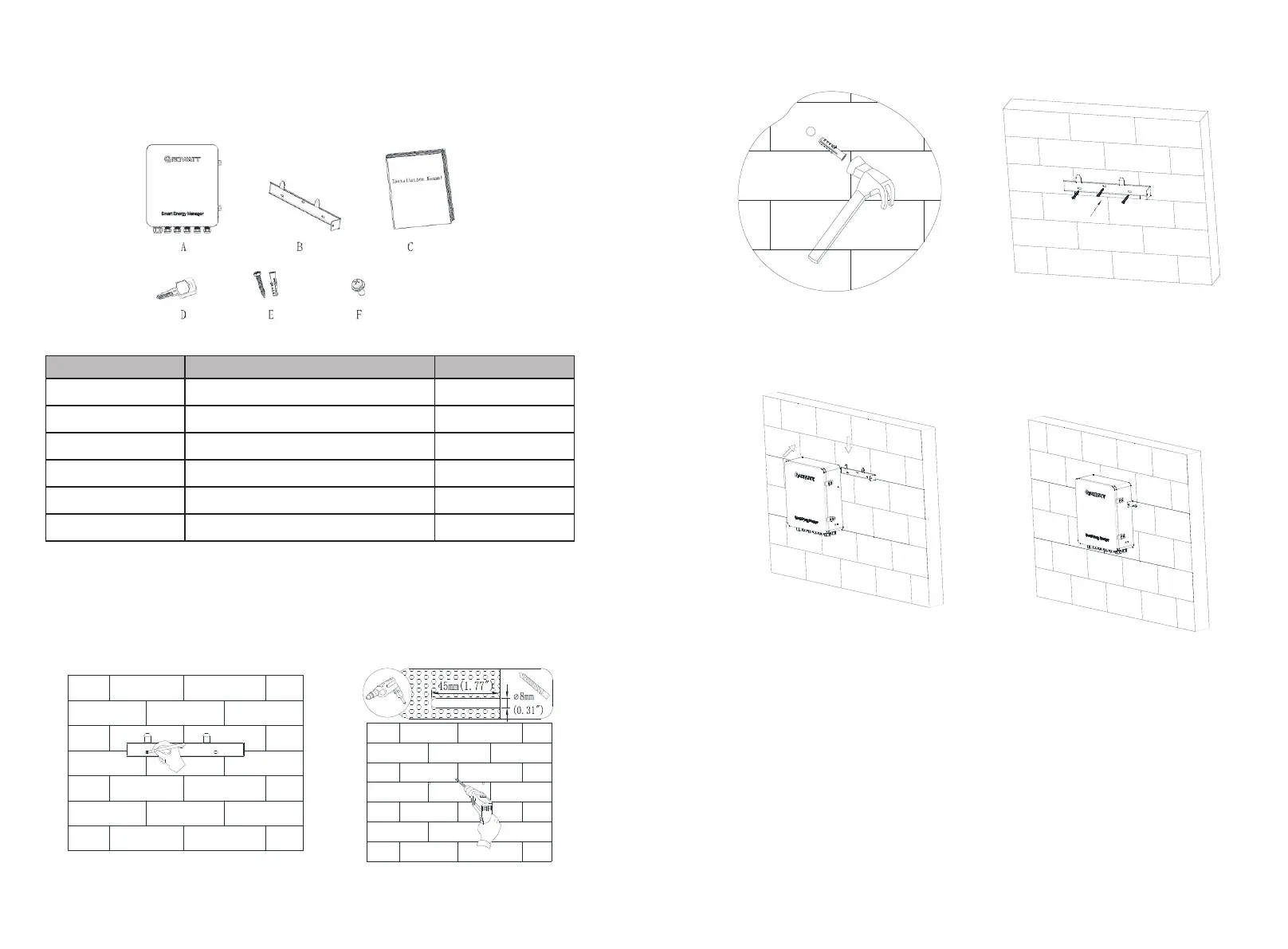
Figure 2-7 Accessory diagram
Referring to the drawing method in the figure below, drill two holes in the wall and insert
the plastic expansion tubes, lock the self-tapping screws on the plastic expansion tubes,
fix the fixed wall hanging of the ShineSEM-X to the wall, and then install the Hang up the
communication box of the smart sub-array, and lock the screws to complete the
installation.
Figure 2-8 Pointing and punching
Figure 2-9 Install the knock-on screw cover and fix the wall mount
Figure 2- 10 Installation and fixing
Note: This product is supplied with a special key to lock the upper cover, which can be
operated by the customer according to the actual situation.
Open the upper cover of the communication box of the smart array , and connect
according to the figure below. In the absence of an electric meter in the ShineSEM-X, the
three current transformers and the voltage sampling interface do not need to be
connected.
The main accessories of the smart array communication box are as follows:
2.3 Unpacking
2.4 Installation
2.5 Wiring instructions
 Loading...