10
9
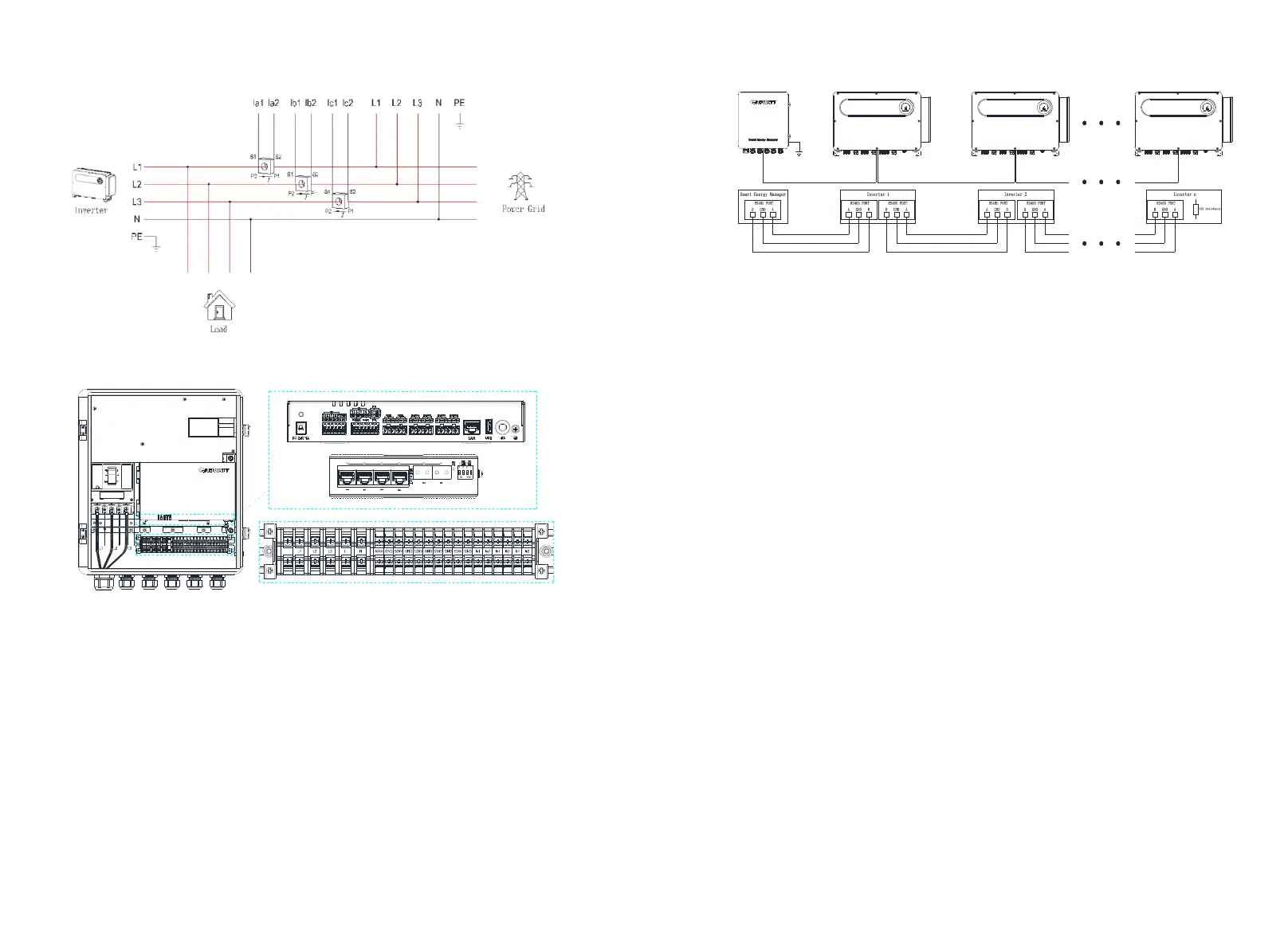
Figure 2-11 Wiring diagram
Figure 2-12 Interface terminal diagram
1. Overall wiring
As can be seen from the figure above, the three CTs and AC voltage sampling lines need
to be placed between the load and the grid to detect the power of the grid-connected
access point in real time. The ShineSEM-X is recommended to be installed near the power
distribution cabinet of the grid. The CT and AC voltage sampling lines are placed in the
power distribution cabinet.
2. RS485 interface
The ShineSEM-X is used to connect the RS485 interface of the inverter. For the wiring
method of multiple inverters, please refer to the following figure. The precautions are as
follows:
(1) The RS485 wire is recommended to use twisted-pair shielded wire, and the shielding
layer is connected to the GND pin of the RS485 interface of the ShineSEM-X and the
inverter.
(2) A maximum of 32 inverters can be connected, that is, n≤32. Refer to the wiring
diagram and connect them hand in hand.
( 3) The collector and the inverter should be connected in a hand-in-hand manner, and
the RS 485 interface of the last inverter should be connected to the grounding terminal
of the casing to prevent the 485 communication from being interfered.
Figure 2- 13 RS485 wiring diagram
3. Current transformer interface
There are P1 and P2 silk screens on both sides of the current transformer to distinguish
the direction. Refer to Figure 2-5 for wiring. The P1 side is close to the grid, and the P2
side is close to the inverter and load. The transformer connection method is as follows:
(1) S1 of inverter L1 phase current transformer CT1 is connected to Ia1, S2 is connected
to Ia2,
(2) S1 of inverter L2 phase current transformer CT2 is connected to Ib1, S2 is connected
to Ib2,
(3) S1 of inverter L3 phase current transformer CT3 is connected to Ic1, S2 is connected
to Ic2,
Precautions:
(1) Before the transformer is installed, its secondary must be connected to the ShineSEM-
X to ensure that the secondary of the transformer is not open.
(2) If the on-site primary busbar is a cable, professional electrical personnel can carry out
live installation; if the primary busbar is a copper bar, the live operation requires a
relatively high level of proficiency for the operator, and insulation protection measures
are required.
(3) When installing the transformer, foreign matter such as impurities and dust must not
fall into the cutting surface of the iron core, so as not to affect the performance of the
transformer.
(4) If the ShineSEM-X is not equipped with an ammeter, no current transformer needs to
be installed.
4. Voltage sampling interface
Connect the voltage sampling line as shown in Figure 2-7. According to the three-phase
four-wire wiring method, L1/L2/L3/N must be connected, otherwise the ShineSEM-X will
not work properly.
5. Network cable interface
Pull a network cable from a router with a network, and plug it directly into the ring
network switch of the communication box of the smart subarray . This interface is used
for remote monitoring. For details, please refer to Chapter 5.
6. Ground terminal
To ensure the reliable operation and personal safety of the ShineSEM-X, the ground
terminal on the housing must be reliably grounded.
Note: Pay attention to the waterproofing of the ground terminal.
 Loading...