In field application wiring, the ShineSEM-X supports PLC communication, and can be
used with multiple inverters for data collection, monitoring, uploading and other
functions. The specific wiring diagram is as follows:
Precautions:
(1) If the on-site primary busbar is a cable, professional electrical personnel can carry out
live installation; if the primary busbar is a copper bar, the live operation requires a
relatively high level of proficiency for the operator, and requires good insulation
protection measures.
(2) When the ShineSEM-X is connected to the power grid, it is necessary to ensure that
the three-phase L1, L2, and L3 of the power grid are connected to the L1, L2, and L3
phases of the ShineSEM-X in sequence.
If there are multiple inverters, a multi-level PLC monitoring system can be formed with
the combiner box. The specific system connection block diagram is as follows:
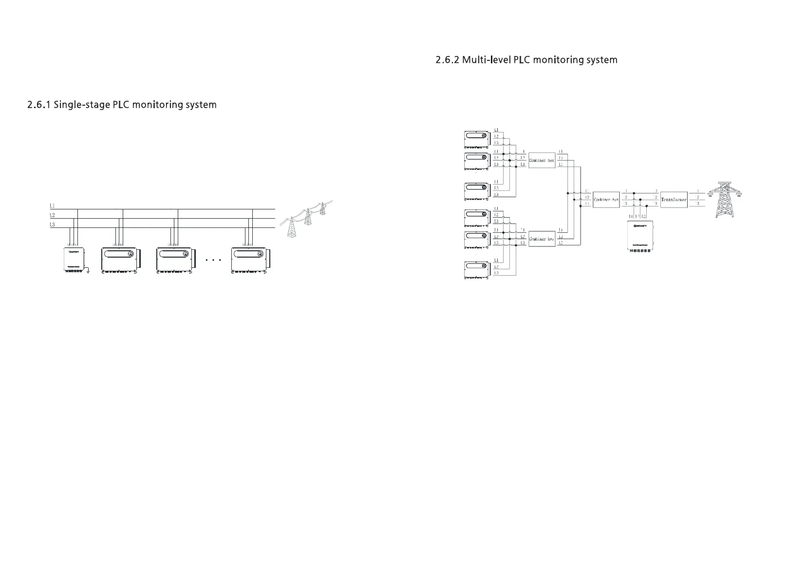
Figure 2-14 Schematic diagram of PLC communication connection
Figure 2-15 PLC cascade system diagram
Precautions:
(1) If the on-site primary busbar is a cable, professional electrical personnel can carry out
live installation; if the primary busbar is a copper bar, the live operation requires a
relatively high level of proficiency for the operator, and requires good insulation
protection measures.
(2) When the ShineSEM-X is connected to the power grid, it is necessary to ensure that
the three-phase L1, L2, and L3 of the power grid are connected to the L1, L2, and L3
phases of the ShineSEM-X in sequence.
(3) The location where the ShineSEM-X is connected must be before the transformer.
11
12
1. Overall wiring
As can be seen from the above figure, the ShineSEM-X is connected to L1, L2, and L3 of
the power grid, and then each inverter is also connected to the power grid in sequence,
and the data is uploaded to the cloud server through PLC communication monitoring.
1. Overall wiring
As can be seen from the cascading method in the above figure, multiple inverters are
connected to the first-level combiner box, then connected to the second-level combiner
box, and then connected to the power grid through the transformer. The ShineSEM-X
must be installed on the transformer Before.
2.6 PLC application system diagram
 Loading...