5
6
The switch is switched off by default at the factory. The power meter and ShineMaster-X
are in a powered off state. The power meter and ShineMaster-X work properly when
powered up.
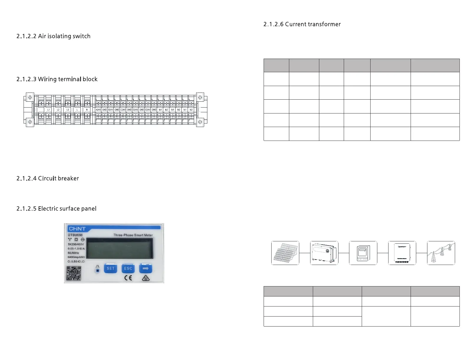
Figure 2-4 Terminal block
21 wiring ports in the terminal block, which are as follows from left to right:
(a) Three-phase voltage output interface (L 1 , L 2 , L 3 )
(b) Single-phase power input interface (L, N)
(c) 24 V voltage output ports (A 24 V, B 24 V, C 24 V, D 24 V, E 24 V, GND)
(d) Current transformer interface (Ia1, Ia2, Ib1, Ib2, Ic1, Ic2).
The factory default is OFF and the three phase input is in the OFF state. After the operator
has connected all the wiring to the intelligent sub-array communication box, turn the
switch upwards so that the switch is ON. Then three phase input will be normal .
The ammeter is an optional component, and it is used with the anti-reflux box
The electrical panel can display various electrical parameters: voltage, current, active
energy, active power, power factor, etc. The display interface and setting parameters can
be switched through the 3 buttons at the bottom of the panel, click "→" to switch to the
next interface, and click "ESC" to switch to the previous interface, see chapter 3.3 for
details.
The ShineSEM-X with different system capacities will be delivered with different types of
open-type current transformers, which are used to detect the current of the grid-
connected access point in the low-voltage power distribution system. The specifications
are shown in the following table:
Note:
1. The total power of inverters or loads in the entire system cannot exceed the
corresponding system capacity of the ShineSEM-X.
2. Under any conditions, the current flowing through the primary side of the current
transformer (CT) cannot exceed its maximum detection range.
3. Avoid running the current transformer in high-humidity environment.
The working principle of the smart array communication box is as follows:
1. The inverter converts the direct current generated by sunlight irradiating the
photovoltaic string into alternating current,
2. The electric energy generated by the inverter can be used for user load or output to
the grid,
3. The ShineSEM-X is located between the inverter, the user load and the grid, and
communicates with the inverter through PLC or RS485 .
The block diagram of photovoltaic grid-connected anti-backflow system is as follows:
A B C D E
Wisdom Subarray
Communication Box
Figure 2-5 Electrometer panel
Figure 2-6 Photovoltaic grid-connected anti-backflow system
2.2 Introduction to working principle
 Loading...