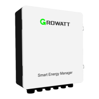
Figure 2-2 Internal structure
The ShineSEM-X is mainly composed of ShineMaster-X, electric meter, air isolating switch,
circuit breaker, and terminal block
The functions of each part are as follows:
1. ShineMaster- X : the control core, which communicates with the inverter and the meter
to realize the functions of remote monitoring, setting, upgrading, and collecting relevant
operating information of the inverter.
2. Electric meter: Real-time monitoring of parameters such as voltage, current and power.
3. Air isolation switch: It can control the start and stop of ShineMaster-X and PLC power
supply .
4. Circuit breaker : Control the start and stop of the three-phase high voltage input .
5. Terminal block: where the user makes connections.
ShineMaster- X status LED lights, which can display the running status of ShineMaster-X.
Figure 2- 3 Indicator lights
A. Power indicator Power
LED
Always off: The power supply is working abnormally;
Steady on: The power supply is working normally.
B.Bluetooth indicator
BLE LED
(not currently supported)
Always off: Bluetooth is not enabled;
1S blinks 1 time, off 1 time: Bluetooth is enabled, but not
connected to the mobile APP ;
Steady on: Bluetooth works normally and is connected to
the mobile APP normally.
Always off: does not support 4G function;
1S blinks 2 times, off 1 time: no SIM card inserted
1S blinks 1 time, off 1 time: 4G network is abnormal or SIM
has no traffic;
Steady on: The 4G network is normal.
Always off: the network is not connected;
1S blinks 1 time, off 1 time: Obtained a valid IP , no
network data interaction. That is, the connection with the
server is abnormal.
E.Status Indicator RUN
LED
Steady off: The system is working normally without any
alarm or fault;
Blinking blue light: the system has an alarm; for example:
abnormal connection to the server, abnormal
communication of monitoring equipment, etc.
Steady red light: There is a system failure. For example: The
SD card is not working properly. The MMC memory chip is
not working properly. The anti-backflow function fails.
Lightning protection alarm, third-party alarm signal, etc.
3
4
A
B C
D
E
A B C D E

 Loading...